Your location:
 /
valves
/
Pressure Reducing Valve
/
Gas Pressure Reducing Valve
/
YK43F Pilot-Operated Oxygen Pressure Reducing Valve
/
valves
/
Pressure Reducing Valve
/
Gas Pressure Reducing Valve
/
YK43F Pilot-Operated Oxygen Pressure Reducing Valve

Mark Classification of Fluid products
- Phone:+86(577)67198981
- Fax:+86(577)67038872
- mobile:+8613388552747
- Sales Email 1:Karrie@shanliuvalve.com
- Sales Email 2:Yannie@shanliuvalve.com
- Sales Email 3:Merry@shanliuvalve.com
- Sales Email 4:Lucas@shanliuvalve.com
- Email:sales@shanliuvalve.com

YK43F Pilot-Operated Oxygen Pressure Reducing Valve
- Model:YK43F-16C/YK43F-25C/YK43F-40C/YK43F-64C/YK43F-16P/YK43F-25P/YK43F-40P/YK43F-64P/YK43F-100P
- Specification:DN15-DN500
- Temperature:≤ 425 ℃
- Medium:Oxygen
- Pressure:1.6Mpa-16Mpa
- Connection method:Flange
- Driving method:spring
- Material:Stainless steel,carbon steel


Add QR code to serve you!
- Product Overview
- Performance Data
- Size Weight
YK43F Pilot-Operated Oxygen Pressure Reducing Valve Overview
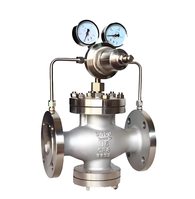
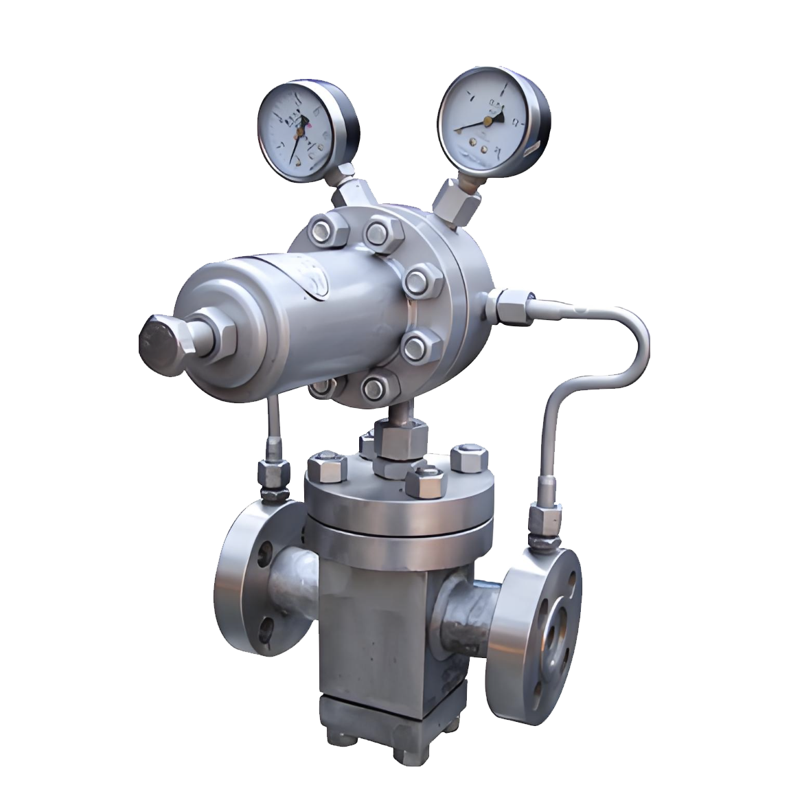
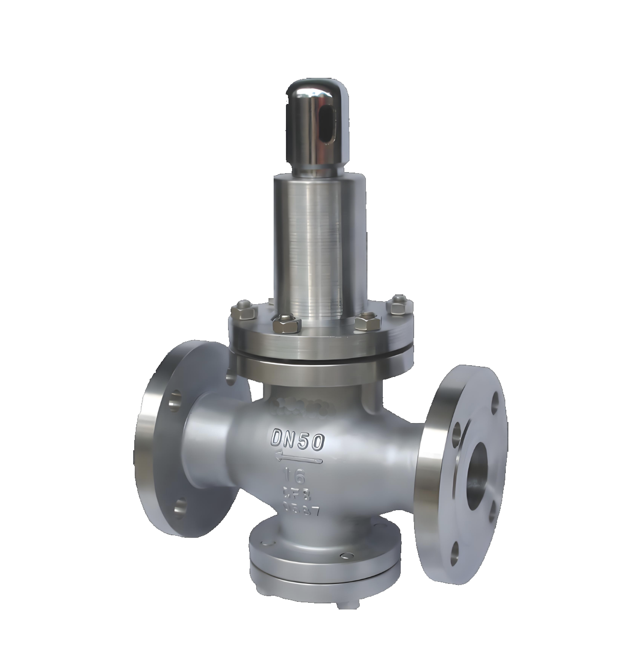
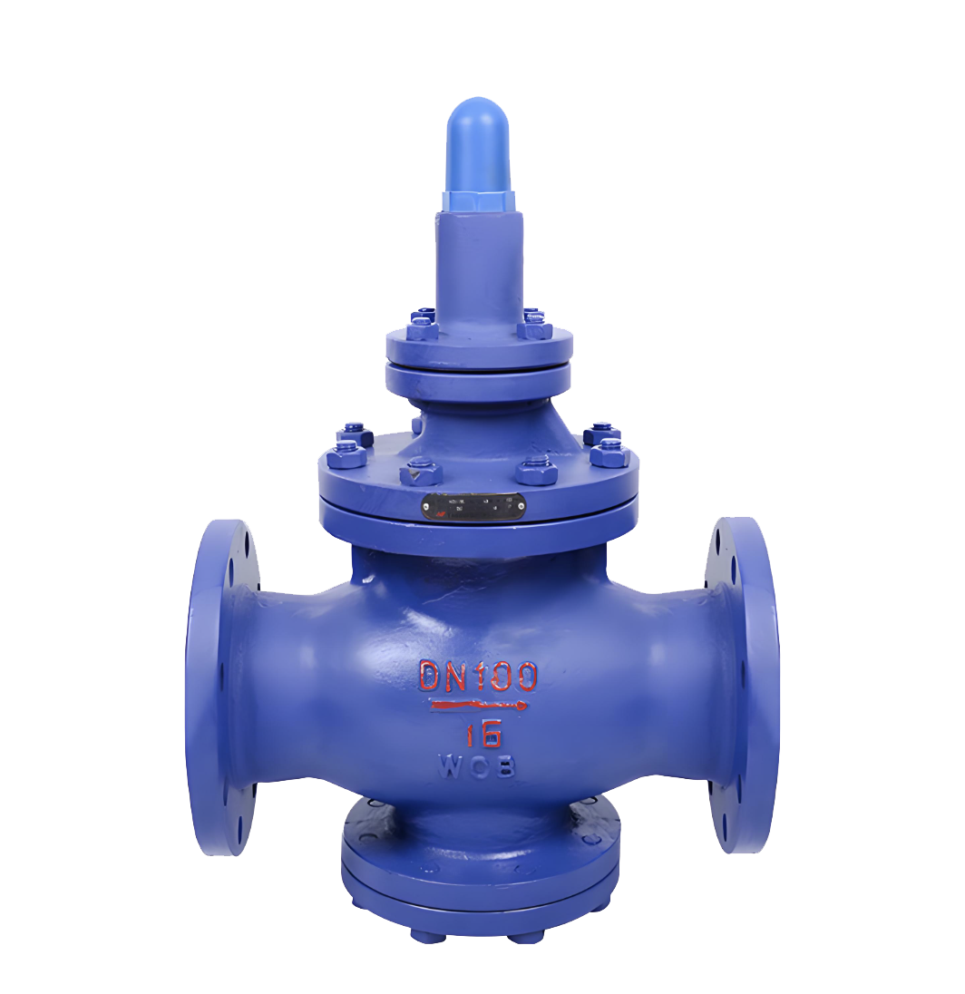
The YK43F pilot-operated oxygen pressure reducing valve is a safety-oriented pressure reducing device specifically designed for high-purity oxygen transmission systems. Adopting a special structure combining pilot control and metal sealing technology, it can stably and accurately reduce the high-pressure oxygen in oxygen cylinders or oxygen supply pipelines to the low-pressure output required by the process. Strictly complying with the special requirements of explosion-proof, oil-free and pollution-proof for oxygen medium, the valve eliminates the risk of combustion and explosion while ensuring pressure control precision through multiple safety designs and material optimization. It is a core safety equipment in fields such as medical oxygen supply, metal cutting, aerospace propulsion and chemical oxidation. The valve is made of oil-free treated brass or stainless steel, equipped with a misoperation-preventive structure and oxygen-specific interfaces. It strictly meets the safety technical specifications for oxygen equipment, serving as a key guarantee for safe pressure reduction and stable supply in high-pressure oxygen systems.
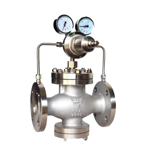
YK43F Pilot-Operated Oxygen Pressure Reducing Valve Product Image
YK43F Pilot-Operated Oxygen Pressure Reducing Valve Features
1. Oxygen-Specific Safety Design
The entire valve is manufactured using oil-free and degreasing processes, with all components strictly degreased, cleaned and hermetically packaged. The flow channel design avoids dead ends where impurities can accumulate. Metal materials compatible with oxygen (such as brass, stainless steel, nickel-based alloys) are selected, eliminating the risk of combustion and explosion caused by oil contamination from the source.
2. Dual Pressure Stabilization and Precision Control
Adopts a two-stage control structure with separate pilot valve and main valve. The pilot stage achieves sensitive detection and amplification of pressure signals, while the main valve stage realizes precise large-flow regulation through a balanced piston. This design can stably reduce the inlet pressure (usually 15-20MPa) to the working pressure of 0.1-1.6MPa, with a control accuracy of ±2%.
3. All-Metal Hard Seal Structure
Key sealing parts adopt metal-to-metal hard seal form (such as stainless steel valve seat and PTFE-enhanced seal ring). It not only ensures the reliability of high-pressure sealing but also avoids the decomposition risk of non-metallic materials in high-pressure pure oxygen environment, providing excellent long-term operational stability.
4. Multiple Safety Protection Mechanisms
Comes standard with a bronze sintered filter to prevent pipeline impurities from entering the pilot system. The outlet end integrates an explosion-proof safety diaphragm or spring-loaded safety valve. The adjusting mechanism is equipped with an anti-loosening locking device. Some models are provided with pressure gauge shockproof fluid and flame arrester interface, forming a complete safety protection system.
5. Professional Operation and Maintenance
Equipped with a fine-adjustment handwheel with a dust cover, enabling stepless pressure regulation and preventing accidental contact. The valve body is marked with a permanent oxygen medium identifier. Maintenance must be performed by professional personnel using special tools. All components comply with the "Oxygen Safety Technical Regulations" standard, with clear regular inspection cycles to ensure safe and controllable whole-life cycle.
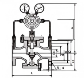
YK43F Pilot-Operated Oxygen Pressure Reducing Valve Structures Diagram
Parts Name Material List
| NO. | Name | Material |
| 1 | body | WCB/304 |
| 2 | Seat and Disc | 2CR13/304 |
| 3 | sleeve | 2Cr13/25Hard Chrome Plating/304 |
| 4 | piston | 2Cr13 Copper Alloy |
| 5 | Pilot Valve Seat and Pilot Valve Stem | 2Cr13/304 |
| 6 | Main Valve Spring | Alloy Wear-Resistant Cast Iron |
| 7 | Pilot Valve Main Spring | 50CrVA |
| 8 | regulating spring | 60Si2Mn |
| 9 | Seal | NBR PTFE |
| 性能规范表Performance Specification | ||
| 公称压力Nominal Pressure | 1.6-16 | MPa |
| 强度试验压力Shell Test | 2.4-24 | |
| 密封试验压力Seal Test | 1.76-17.6 | |
| 适用温度Suitable Temp. | ≤425 | ℃ |
Dimensions Standard Requirements
1. The structural length of the valve shall conform to the standard GB/T12221.
2. The connecting flange shall conform to the standard GB/T 17241.6
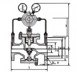
YK43F Pilot-Operated Oxygen Pressure Reducing Valve View Drawing
YK43F Pilot-Operated Oxygen Pressure Reducing Valve Dimensions Table PN1.6-4.0
| 公称通径DN | 外形尺寸 | |||
| L | H | HI | ||
| 1.6/2.5MPa | 4.0MPa | |||
| 15 | 160 | 180 | 290 | 90 |
| 20 | 160 | 180 | 300 | 98 |
| 25 | 180 | 200 | 300 | 110 |
| 32 | 200 | 220 | 300 | 110 |
| 40 | 220 | 240 | 320 | 125 |
| 50 | 250 | 270 | 320 | 125 |
| 65 | 280 | 300 | 325 | 130 |
| 80 | 310 | 330 | 365 | 160 |
| 100 | 350 | 380 | 365 | 170 |
| 125 | 400 | 450 | 475 | 200 |
| 150 | 450 | 500 | 475 | 210 |
| 200 | 500 | 550 | 515 | 240 |
| 250 | 650 | 560 | 290 | |
| 300 | 800 | 705 | 335 | |
| 350 | 850 | 745 | 375 | |
| 400 | 900 | 780 | 405 | |
| 450 | 900 | 730 | 455 | |
| 500 | 950 | 835 | 465 | |
YK43F Pilot-Operated Oxygen Pressure Reducing Valve Dimensions Table PN6.4-16.0
| 公称通径DN | 外形尺寸 | |||
| L | H | HI | ||
| 6.4MPa | 10.0/16.0MPa | |||
| 15 | 180 | 180 | 300 | 100 |
| 20 | 180 | 200 | 310 | 105 |
| 25 | 200 | 220 | 31 | 120 |
| 32 | 220 | 230 | 310 | 120 |
| 40 | 240 | 240 | 335 | 135 |
| 50 | 270 | 300 | 335 | 135 |
| 65 | 300 | 340 | 340 | 140 |
| 80 | 330 | 360 | 380 | 170 |
| 100 | 380 | 380 | 185 | |
| 125 | 450 | 490 | 215 | |
| 150 | 500 | 490 | 225 | |
| 200 | 550 | 535 | 260 | |
| 250 | 650 | 580 | 310 | |
| 300 | 800 | 725 | 355 | |
| 350 | 850 | 765 | 395 | |
| 400 | 900 | 800 | 435 | |
| 500 | 950 | 855 | 495 | |
YK43F Pilot-Operated Piston Type Gas Pressure Reducing Valve Flow Coefficient
| DN | 15 | 20 | 25 | 32 | 40 | 50 | 65 | 80 | 100 | 125 | 150 | 200 | 250 | 300 | 350 | 400 | 500 |
| Cv | 1 | 2.5 | 4 | 6.5 | 9 | 16 | 25 | 36 | 64 | 100 | 140 | 250 | 400 | 570 | 780 | 1020 | 1500 |
-
 YK43F High-Pressure Gas Pressure Reducing Valve
Model:
YK43F-16C/YK43F-25C/YK43F-40C/YK43F-64C/YK43F-16P/YK43F-25P/YK43F-40P/YK43F-64P/YK43F-100PSpecification:
DN15-DN500Pressure:
1.6Mpa-16MpaMaterial:
Cast steel 、stainless steel,forged steel -
 Y42F Stainless Steel Pressure Reducing Valve
Model:
Y42F-16P/Y42F-25P/Y42F-40PSpecification:
DN20-DN200Pressure:
PN16,PN25,PN40Material:
Stainless steel -
 Y43X Pilot-Operated Piston Pressure Reducing Valve
Model:
Y43X-10C/Y43X-16C/Y43X-10P/Y43X-16PSpecification:
DN50-DN400Pressure:
PN10,PN16Material:
Stainless steel,carbon steel

Is the noise from the pressure reducing valve disturbing? Understand the 3 fundamental reasons and solutions in one article
The harsh noise generated by pressure reducing valves during operation is not only an environmental pollution problem, but also a precursor to equipment failure. This article will delve into the three fundamental causes of noise generated by pressure reducing valves - mechanical vibration noise, fluid dynamics noise, and aerodynamic noise, and provide professional solutions.
1、 Mechanical vibration noise: a test of design and process
Mechanical vibration noise is the most common type of noise in pressure reducing valves, mainly divided into two forms:
1. Low frequency vibration noise
Causes:
Medium jet and pressure pulsation
The outlet flow rate of the valve is too fast
Unreasonable pipeline layout
Insufficient rigidity of moving parts inside the valve
2. High frequency vibration noise (resonance phenomenon)
Causes:
The natural frequency of the valve coincides with the excitation frequency of the medium
Easy to occur within a specific decompression range
Sensitive to changes in working conditions, with significant noise fluctuations
Solution:
Optimize the clearance design between the liner and valve stem
Improve machining accuracy
Adjust the natural frequency of the valve
Enhance the rigidity of active components
Select appropriate damping materials
2、 Fluid Dynamics Noise: Challenges in Fluid Control
The turbulence and eddies generated when the fluid passes through the pressure reducing valve can cause significant noise problems.
1. Turbulent noise
Features: Low frequency, low noise level
Cause: Interaction between turbulent fluid and the inner surface of valves/pipelines
Impact: Usually does not constitute a serious noise problem
2. Cavitation noise (the most harmful)
Production mechanism:
During the depressurization process, the fluid flow velocity reaches the critical value
The liquid begins to vaporize, producing bubbles
Bubble explosion under pressure generates shock waves
Local instantaneous pressure can reach 196 MPa
Key data:
Initial value of Δ p: the critical pressure reduction value at which liquid begins to cavitation
Exceeding this value leads to a sharp increase in noise
Preventive measures:
Control the actual pressure reduction value below the critical value
Optimize the design of valve disc fluid direction
Adopting a multi-stage decompression structure
Choose anti cavitation materials
3、 Aerodynamic noise: characteristics of compressible fluids
When compressible fluids such as steam pass through pressure reducing areas, unique noise issues arise:
Production principle:
Conversion of fluid mechanical energy into sound energy
Interaction between high-speed airflow and valve structure
Sudden pressure changes cause gas expansion and sound emission
Control method:
Optimize the design of pressure reducing flow channels
Using mufflers or diffusers
Control the outlet flow rate
Reasonably set back pressure
Comprehensive solutions and selection suggestions
Preventive measures during the design phase
Parameter optimization: Accurately calculate operating parameters to ensure that the pressure reduction value is within the design range
Structural design: Adopting streamlined flow channels to reduce turbulence generation
Material selection: Select special alloys with high rigidity and cavitation resistance
Frequency analysis: avoid the natural frequency of the valve coinciding with the excitation frequency
Key points for installation and maintenance
Correct installation: Ensure the length of the front and rear straight pipe sections to avoid sharp bends
Regular testing: Establish a noise monitoring mechanism to detect problems early on
Timely maintenance: replace worn parts and maintain the best condition of the valve
Brand selection recommendation
High pressure differential operating condition: choose multi-stage pressure reducing valve
Liquid medium: focus on anti cavitation design
Gas/Steam: Focus on Aerodynamic Optimization
Sensitive environment: Choose a low-noise dedicated model
Professional Technical Summary
The essence of the noise problem of pressure reducing valves is the process of energy conversion and release. Fundamentally, all noise issues are closely related to the rationality of valve design, manufacturing process accuracy, and compatibility with operating conditions. Through scientific selection, correct installation, and standardized maintenance, it is entirely possible to control the noise of the pressure reducing valve within an acceptable range.
Immediate action suggestion: If you are troubled by pressure reducing valve noise, it is recommended to first record the noise characteristics (frequency, time period, change pattern), check whether the operating parameters deviate from the design values, and promptly contact professional technicians for diagnosis and treatment.
Keywords of this article: pressure reducing valve noise, mechanical vibration noise, cavitation noise, fluid dynamics noise, pressure reducing valve failure, valve noise reduction, industrial noise control, equipment maintenance
Extended reading: For more professional knowledge about industrial valve selection and maintenance, please follow our technical column to obtain the latest solutions and industry practice cases.
Address:No. 1, Linxia Road, Sanqiao Industrial Zone, Oubei Sub-district, Yongjia County, Zhejiang Province| Switchboard:0577-67198981| mobile:+8613388552747| Email:sales@shanliuvalve.com|
COPYRIGHT © Zhejiang Shanliu Valve Technology Co., Ltd. Main Business: Water Valve Industrial valve|
浙ICP备2026020749号![]()