Your location:
 /
valves
/
Pressure Reducing Valve
/
Branch Pressure Reducing Valve
/
YZ13X NPT Pressure Reducing Valve with Pressure Gauge
/
valves
/
Pressure Reducing Valve
/
Branch Pressure Reducing Valve
/
YZ13X NPT Pressure Reducing Valve with Pressure Gauge

Mark Classification of Fluid products
- Phone:+86(577)67198981
- Fax:+86(577)67038872
- mobile:+8613388552747
- Sales Email 1:Karrie@shanliuvalve.com
- Sales Email 2:Yannie@shanliuvalve.com
- Sales Email 3:Merry@shanliuvalve.com
- Sales Email 4:Lucas@shanliuvalve.com
- Email:sales@shanliuvalve.com

YZ13X NPT Pressure Reducing Valve with Pressure Gauge
- Model:YZ13X-10P/YZ13X-16P/YZ13X-10C/YZ13X-16C
- Specification:DN15-DN65
- Temperature:≤80℃
- Medium:Water and media similar to water.
- Pressure:PN10,PN16
- Connection method:NPT
- Driving method:Automated
- Material:Stainless steel


Add QR code to serve you!
- Product Overview
- Performance Data
- Size Weight
YZ13X NPT Pressure Reducing Valve with Pressure Gauge Overview
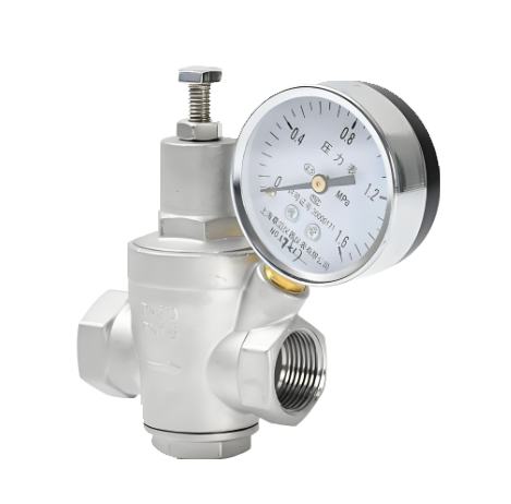
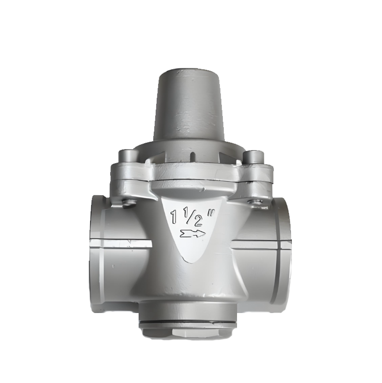
The YZ13X NPT Pressure Reducing Valve with Pressure Gauge is a direct-acting branch pipe pressure reducing device integrated with pressure monitoring function. Adopting an integrated design of spring-diaphragm mechanical structure and built-in pressure gauge, it can accurately reduce the unstable inlet pressure to the set value while displaying the outlet pressure in real time during pressure adjustment. Through its built-in pressure sensing system, the valve automatically balances the pipeline pressure and provides users with an intuitive pressure monitoring method. Its compact structure and internal thread interface are specifically optimized for instrument pipelines, equipment inlets and space-constrained branch pipe systems. It is widely used in HVAC systems, water supply and drainage systems, industrial equipment supporting facilities, gas control and other occasions that require precise pressure management and real-time monitoring.
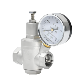
YZ13X NPT Pressure Reducing Valve with Pressure Gauge Product Image
YZ13X NPT Pressure Reducing Valve with Pressure Gauge Features
1. Integrated Pressure Monitoring Design
A high-precision mechanical pressure gauge (usually Class 1.6 accuracy) is integrated on the top of the valve, which can display the outlet pressure in real time without the need for additional pressure gauge installation or connecting pipelines. The dial is equipped with anti-vibration liquid design, adapting to vibrating environments, providing stable and reliable visual monitoring, and facilitating pressure calibration and system diagnosis.
2. Compact Internal Thread Connection Structure
Adopting an integral stainless steel or brass forged valve body with standard internal thread interfaces (such as G1/2", G3/4"), the structure is highly integrated and does not occupy extra space during installation. Its lightweight design supports flexible horizontal or vertical installation, making it especially suitable for equipment interfaces, branch pipelines and centralized piping scenarios of instrument panels.
3. Direct-Acting Sensitive Adjustment
Equipped with a linkage mechanism of precision diaphragm and pressure regulating spring, it responds quickly to pressure fluctuations and can automatically maintain stable set pressure. The adjusting knob is equipped with a scale indicator, supporting stepless pressure regulation (common range 0.05-0.8MPa). The adjustment process is synchronized with the pressure gauge display, realizing "what you see is what you get" precise control.
4. Built-In Filtration and Anti-Interference Design
The water inlet end of the valve is standard equipped with a stainless steel filter screen (above 100 meshes), which effectively intercepts pipeline impurities and protects the valve core and pressure gauge transmission mechanism. The pressure gauge connection part adopts diaphragm sealing or damping design, reducing the impact of medium pulses on the pressure gauge pointer and extending the service life of the instrument.
5. Convenient Maintenance and Safety Reliability
The pressure gauge and valve body adopt a separable connection, supporting independent calibration or replacement. The key sealing components of the valve adopt a modular design, and no overall disassembly is required during maintenance. All flow-passing parts of the valve are made of corrosion-resistant materials, suitable for cold water, hot water, compressed air and non-corrosive liquid media, ensuring long-term stable operation.
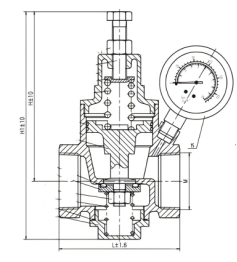
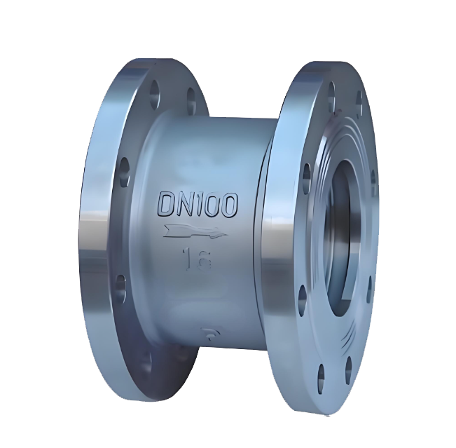
YZ13X NPT Pressure Reducing Valve with Pressure Gauge Structure Diagram
Parts Name Material List
| NO. | Name | Material |
| 1 | body | stainless steel |
| 2 | piston | stainless steel |
| 3 | seal ring | NBR |
| 4 | bolt | 304 |
| Performance Specification | ||
| Nominal Pressure | 1.0/1.6 | MPa |
| Shell Test | 1.5/2.4 | |
| Seal Test | 1.1/1.76 | |
| Suitable Temp. | ≤80 | ℃ |
Dimensions Standard Requirements
1. The structural length of the valve shall conform to the standard GB/T12221.
2. The connecting flange shall conform to the standard GB/T 9113.
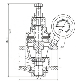
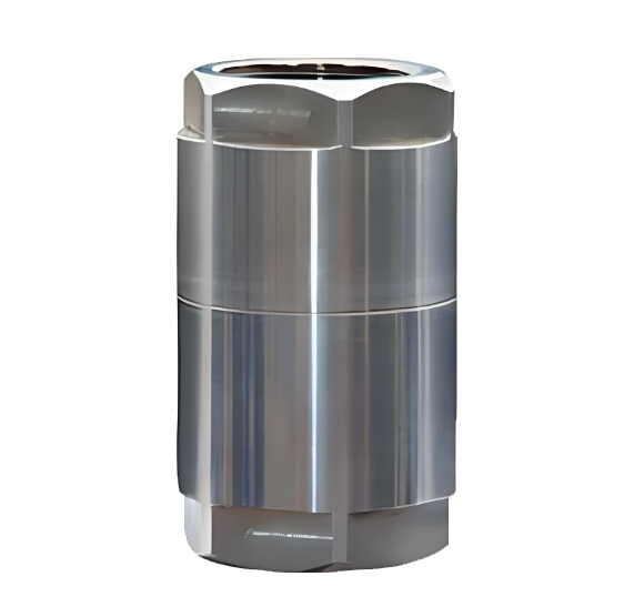
YZ13X NPT Pressure Reducing Valve with Pressure Gauge View Drawing
YZ13X NPT Pressure Reducing Valve with Pressure Gauge Dimensions Table
| DN | M | L | H | H1 |
| 65 | BSPT 21/2” | 125 | 168 | 224 |
| 50 | BSPT 2” | 123 | 143 | 197 |
| 40 | BSPT 11/2” | 102 | 143 | 192 |
| 32 | BSPT 11/4” | 90 | 110 | 149 |
| 25 | BSPT 1” | 85 | 110 | 145 |
| 20 | BSPT 3/4” | 75 | 100 | 127 |
| 15 | BSPT 1/2” | 70 | 100 | 125 |
-
 YZ11X Stainless Steel Branch Pipe Pressure Reducing Valve
Model:
YZ11X-10P/YZ11X-16PSpecification:
DN15-DN50Pressure:
PN10,PN16Material:
Stainless steel -
 YB43X Proportional Pressure Reducing Valve
Model:
YB43X-10T/YB43X-16T/YB43X-10P/YB43X-16PSpecification:
DN25-200Pressure:
PN10,PN16Material:
Brass,Stainless Steel -
 YB13 Internal Thread Proportional Pressure Reducing Valve
Model:
YB13-6P/YB13-10P/YB13-16P/YB13-25PSpecification:
DN50-500Pressure:
PN6,PN10,PN16,PN25Material:
Cast Iron、Cast Steel、Stainless Steel

Is the noise from the pressure reducing valve disturbing? Understand the 3 fundamental reasons and solutions in one article
The harsh noise generated by pressure reducing valves during operation is not only an environmental pollution problem, but also a precursor to equipment failure. This article will delve into the three fundamental causes of noise generated by pressure reducing valves - mechanical vibration noise, fluid dynamics noise, and aerodynamic noise, and provide professional solutions.
1、 Mechanical vibration noise: a test of design and process
Mechanical vibration noise is the most common type of noise in pressure reducing valves, mainly divided into two forms:
1. Low frequency vibration noise
Causes:
Medium jet and pressure pulsation
The outlet flow rate of the valve is too fast
Unreasonable pipeline layout
Insufficient rigidity of moving parts inside the valve
2. High frequency vibration noise (resonance phenomenon)
Causes:
The natural frequency of the valve coincides with the excitation frequency of the medium
Easy to occur within a specific decompression range
Sensitive to changes in working conditions, with significant noise fluctuations
Solution:
Optimize the clearance design between the liner and valve stem
Improve machining accuracy
Adjust the natural frequency of the valve
Enhance the rigidity of active components
Select appropriate damping materials
2、 Fluid Dynamics Noise: Challenges in Fluid Control
The turbulence and eddies generated when the fluid passes through the pressure reducing valve can cause significant noise problems.
1. Turbulent noise
Features: Low frequency, low noise level
Cause: Interaction between turbulent fluid and the inner surface of valves/pipelines
Impact: Usually does not constitute a serious noise problem
2. Cavitation noise (the most harmful)
Production mechanism:
During the depressurization process, the fluid flow velocity reaches the critical value
The liquid begins to vaporize, producing bubbles
Bubble explosion under pressure generates shock waves
Local instantaneous pressure can reach 196 MPa
Key data:
Initial value of Δ p: the critical pressure reduction value at which liquid begins to cavitation
Exceeding this value leads to a sharp increase in noise
Preventive measures:
Control the actual pressure reduction value below the critical value
Optimize the design of valve disc fluid direction
Adopting a multi-stage decompression structure
Choose anti cavitation materials
3、 Aerodynamic noise: characteristics of compressible fluids
When compressible fluids such as steam pass through pressure reducing areas, unique noise issues arise:
Production principle:
Conversion of fluid mechanical energy into sound energy
Interaction between high-speed airflow and valve structure
Sudden pressure changes cause gas expansion and sound emission
Control method:
Optimize the design of pressure reducing flow channels
Using mufflers or diffusers
Control the outlet flow rate
Reasonably set back pressure
Comprehensive solutions and selection suggestions
Preventive measures during the design phase
Parameter optimization: Accurately calculate operating parameters to ensure that the pressure reduction value is within the design range
Structural design: Adopting streamlined flow channels to reduce turbulence generation
Material selection: Select special alloys with high rigidity and cavitation resistance
Frequency analysis: avoid the natural frequency of the valve coinciding with the excitation frequency
Key points for installation and maintenance
Correct installation: Ensure the length of the front and rear straight pipe sections to avoid sharp bends
Regular testing: Establish a noise monitoring mechanism to detect problems early on
Timely maintenance: replace worn parts and maintain the best condition of the valve
Brand selection recommendation
High pressure differential operating condition: choose multi-stage pressure reducing valve
Liquid medium: focus on anti cavitation design
Gas/Steam: Focus on Aerodynamic Optimization
Sensitive environment: Choose a low-noise dedicated model
Professional Technical Summary
The essence of the noise problem of pressure reducing valves is the process of energy conversion and release. Fundamentally, all noise issues are closely related to the rationality of valve design, manufacturing process accuracy, and compatibility with operating conditions. Through scientific selection, correct installation, and standardized maintenance, it is entirely possible to control the noise of the pressure reducing valve within an acceptable range.
Immediate action suggestion: If you are troubled by pressure reducing valve noise, it is recommended to first record the noise characteristics (frequency, time period, change pattern), check whether the operating parameters deviate from the design values, and promptly contact professional technicians for diagnosis and treatment.
Keywords of this article: pressure reducing valve noise, mechanical vibration noise, cavitation noise, fluid dynamics noise, pressure reducing valve failure, valve noise reduction, industrial noise control, equipment maintenance
Extended reading: For more professional knowledge about industrial valve selection and maintenance, please follow our technical column to obtain the latest solutions and industry practice cases.
Address:No. 1, Linxia Road, Sanqiao Industrial Zone, Oubei Sub-district, Yongjia County, Zhejiang Province| Switchboard:0577-67198981| mobile:+8613388552747| Email:sales@shanliuvalve.com|
COPYRIGHT © Zhejiang Shanliu Valve Technology Co., Ltd. Main Business: Water Valve Industrial valve|
浙ICP备2026020749号![]()