Your location:
 /
valves
/
Gate Valve
/
hard seal gate valve
/
Z41W Bronze Gate Valve
/
valves
/
Gate Valve
/
hard seal gate valve
/
Z41W Bronze Gate Valve

Mark Classification of Fluid products
- Phone:+86(577)67198981
- Fax:+86(577)67038872
- mobile:+8613388552747
- Sales Email 1:Karrie@shanliuvalve.com
- Sales Email 2:Yannie@shanliuvalve.com
- Sales Email 3:Merry@shanliuvalve.com
- Sales Email 4:Lucas@shanliuvalve.com
- Email:sales@shanliuvalve.com

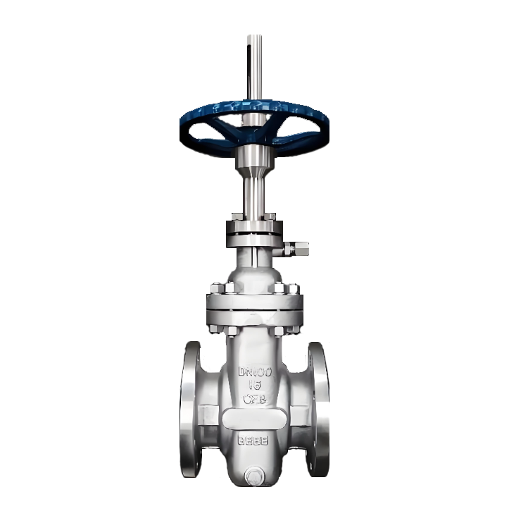
Z41W Bronze Gate Valve
- Model:Z41W-16T/Z41W-25T
- Specification:DN15-DN600
- Temperature:-40~500℃
- Medium: water, seawater, steam, oil and similar liquids, gases.
- Pressure:PN16-PN25
- Connection method:flange
- Driving method: manual, bevel gear transmission, and electric
- Material:Aluminum nickel bronze


Add QR code to serve you!
- Product Overview
- Performance Data
- Size Weight
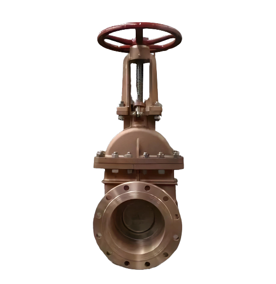
Z41W bronze gate valve is a rising stem wedge gate valve made of high-quality bronze material and connected by flanges. It drives the valve stem to rise and fall through the handwheel, driving the wedge gate to move vertically and achieve the opening and closing of the pipeline. The main components such as the valve body, valve cover, and gate are made of high-strength tin bronze or aluminum bronze casting, which has excellent corrosion resistance. The sealing surface is directly processed from bronze valve body material ("W" shape), forming a hard metal to metal seal. This valve is designed specifically for ships and marine engineering pipelines with media such as seawater, fresh water, and steam, and is an ideal choice for corrosion-resistant conditions. Widely used in shipbuilding and repair, offshore platforms, port facilities, coastal industries, seawater desalination systems, and chemical pipelines. Specially suitable for pipeline systems transporting seawater, fresh water, steam, oil products, and weakly corrosive media, as a cut-off device for manually controlling fluid flow. Its excellent resistance to seawater corrosion makes it an ideal choice for ship ballast water, seawater cooling, and fire protection systems.
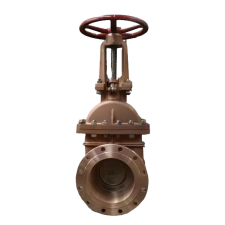
Z41W Bronze Gate Valve Product Drawing
Features:
1. High quality bronze material with excellent corrosion resistance
The main components such as the valve body, valve cover, and gate are made of high-strength tin bronze (such as CAC406) or aluminum bronze (such as CAC703) casting, which has excellent resistance to seawater corrosion, biological adhesion, and good wear resistance, especially suitable for marine environments and corrosive media working conditions.
2. Clear stem structure, intuitive valve position
The valve stem rises and falls with the gate, and the operator can accurately determine the valve opening by observing the height of the valve stem extension, which facilitates system process control and safety management.
3. Valve body sealing surface ("W" type)
The sealing surface is directly processed from bronze valve body material, which is economical, practical, wear-resistant, and suitable for conventional media such as seawater, fresh water, steam, and oil.
4. Flange connection, stable and reliable
Using standard flange connections (such as GB/T 17241.6, JIS B2210, or ANSI B16.24), the connection strength is high, the sealing performance is good, and it is easy to install and disassemble.
5. Full bore design with low flow resistance
Adopting a full bore flow channel, the medium has low flow resistance and pressure loss, making it suitable for high flow conveying systems.
6. The valve stem seal is reliable
Adopting multi-layer packing or O-ring sealing, and equipped with an upper sealing structure, the packing can be replaced online when the valve is fully open for easy maintenance.
7. Wide applicable temperature range
Bronze material is suitable for medium temperatures typically ≤ 200 ℃, meeting the requirements of hot water, steam, and various industrial medium working conditions
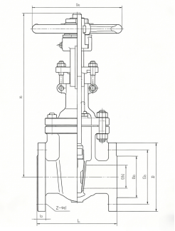
Z41W Bronze Gate Valve Structural Drawing
Part Name Material:
| 序号No | 零部件part name | 常用材质material |
| 1 | 阀体 Body | 青铜C95400/ZCuSn10Zn2/ZCuSn5Pb5Zn5 BronzeC95400/ZCuSn10Zn2/ZCuSn5Pb5Zn5 |
| 2 | 阀盖 Bonnet | 青铜C95400/ZCuSn10Zn2 BronzeC95400/ZCuSn10Zn2 |
| 3 | 阀板 Wedge | 青铜C95400/ZCuSn10Zn2 BronzeC95400/ZCuSn10Zn2 |
| 4 | 阀杆 Stem | 不锈钢2Cr13/304/316 Stainless Steel 2Cr13/304/316 |
| 6 | 填料 Gland Packing | 柔性石墨/石棉盘根/PTFE Flexible Graphite/Asbestos Packing/PTFE |
| 7 | 填料压盖 Gland | 青铜/铸铁 Bronze/Cast Iron |
| 8 | 填料压盖螺母 Gland Nut | 碳钢/不锈钢 Carbon Steel/Stainless Steel |
| 9 | 手轮 Handwheel | 铸铁HT200 Cast Iron HT200 |
| 10 | 手轮螺母 Handwheel Nut | 碳钢 Carbon Steel |
| 11 | 油杯 Oil Cup | 黄铜/塑料 Brass/Plastic |
| 12 | 阀盖垫片 Gasket | 石棉橡胶/石墨复合垫片 Asbestos Rubber/Graphite Composite Gasket |
| 13 | 止推垫圈 Thrust Washer | 青铜/不锈钢 Bronze/Stainless Steel |
Performance Specifications Table
| 型号Model | 公称压力(MPa)Nominal Pressure (MPa) | 实验压力 Experimental pressure | 工作温度(℃)Operating Temperature | 适用介质Applicable Media | |||||
| 强度水(MPa)Strength Water (MPa) | 密封(水)空气(MPa)Seal (Water) Air (MPa) | 低压密封空气(MPa) Low Pressure Seal Air (MPa) | |||||||
| Z41H-16C Z41W-16P(R) | 1.6 | 2.4 | 1.8 | 0.6 | ≤425 | 硝酸类Nitric acid compounds | |||
| Z41W-25P(R) | 2.5 | 3.8 | 2.8 | 0.6 | ≤200 | 醋酸类Nitric acid compounds | |||
| Z41W-40P(R) | 4.0 | 6.0 | 4.4 | 0.6 | ≤200 | 硝酸类Nitric acid compounds | |||
| Z41W-64P(R) | 6.4 | 9.6 | 7.0 | 0.6 | ≤200 | 醋酸类Nitric acid compounds | |||

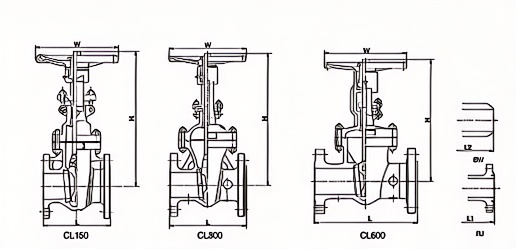
Z41W Bronze Gate Valve
Dimension Chart
CL150
| 现格(NP3)Current Patternt (NP3) | In | 2 | 212 | 3 | 4 | 5 | 6 | 8 | 10 | 12 | 14 | 16 | 18 | 20 | 24 | 28 | 30 | 32 | 36 | 40 | 42 | 48 | 60 |
| 结构长度Structural Length | L | 178 | 190 | 203 | 229 | 254 | 267 | 222 | 330 | 358 | 381 | 408 | 432 | 457 | 508 | 610 | 610 | 680 | 711 | 762 | 787 | 914 | 1097 |
| L1 | 191 | 203 | 216 | 241 | 267 | 279 | 305 | 343 | 368 | 384 | 419 | 446 | 470 | 621 | - | - | - | - | - | - | - | - | |
| L | 216 | 241 | 283 | 205 | 381 | 402 | 419 | 457 | 602 | 572 | 610 | 860 | 711 | 813 | 914 | 914 | 965 | 1060 | 1067 | 1116 | - | ||
| 中 心 高 度Center Height | H | 341 | 371 | 402 | 472 | 630 | S87 | 743 | 904 | 1047 | 1172 | 1287 | 433 | 1690 | 1898/ | 2050 | 2330 | 2S33 | 2800 | 一 | - | - | |
| 手轮直径Handwheel diameter | W | 200 | 200 | 250 | 280 | 300 | 300 | 350 | 400 | 450 | 500 | 600 | 880 | 750 | 800 | 一 | - | 二 | |||||
| 重量weight | 20 | 30 | 33 | 49 | 60 | 75 | 120 | 205 | 290 | 400 | 511 | 850 | 789 | 1200 | 1800 | 2580 | 3060 | 3500 | - | - | - | - | |
CL300
| 现格(NPS) nCurrent Pattern | in | 2 | 212 | 3 | 4 | 5 | 6 | 8 | 10 | 12 | 14 | 18 | 18 | 20 | 24 | 28 | 30 | 32 | 36 |
| 结构长度Structural Length | L | 216 | 241 | 283 | 305 | 381 | 403 | 419 | 457 | 502 | 762 | 838 | 914 | 991 | 1143 | 1346 | 1397 | 1524 | 1727 |
| L1 | 232 | 267 | 298 | 321 | 397 | 419 | 435 | 473 | 518 | 778 | 854 | 930 | 1010 | 1165 | 1371 | 1422 | 1652 | 1765 | |
| L | 216 | 241 | 283 | 305 | 381 | 403 | 419 | 4S7 | 502 | 762 | 838 | 914 | 991 | 1143 | 1346 | 1397 | 1624 | 1727 | |
| 中心高度 Center Height | H | 345 | 376 | 407 | 478 | 635 | 618 | 765 | 929 | 1094 | 1188 | 1320 | 1455 | 1860 | 2030 | - | - | - | |
| 手轮直径Handwheel diameter | W | 200 | 200 | 250 | 300 | 300 | 350 | 400 | 450 | 500 | 550 | 680 | 750 | 820 | - | - | 一 | ||
| 重量weight | 24 | 38 | 47 | 69 | 89 | 123 | 196 | 333 | 440 | 710 | 950 | 1405 | 1720 | 2770 | 3312 | 4100 | 6200 | 6700 | |
CL600
| 现格NPS)Current Patternt (NP3) | in | 2 | 2/2 | 3 | 4 | 6 | 6 | B | 10 | 12 | 14 | 16 | 18 | 20 | 24 | 26 | 30 | 32 | 38 |
| 结构长度Structural Length | L | 292 | 330 | 356 | 432 | 508 | 659 | 680 | 787 | 638 | 889 | 991 | 1092 | 1184 | 1397 | 1549 | 1651 | 1778 | 2083 |
| L1 | 285 | 333 | 359 | 435 | 511 | 662 | 664 | 791 | 841 | 892 | 894 | 1095 | 1200 | 1407 | 1562 | 1684 | 1794 | 2006 | |
| L | 292 | 230 | 356 | 432 | 508 | 659 | 680 | 787 | 838 | 889 | 891 | 1092 | 1194 | 1397 | 1649 | 1651 | 1778 | 2083 | |
| 中心高度Center Height | H | 377 | 443 | 46S | S26 | 610 | 672 | 820 | 983 | 1120 | 1283 | 1429 | 1572 | 1757 | 1985 | 2230 | 2475 | 2300 | 2050 |
| 手轮直径Handwheel diameter | W | 200 | 250 | 280 | 300 | 400 | 450 | 500 | 680 | 760 | 700 | - | - | - | - | - | - | - | |
| 重量weight | 39 | 52 | 88 | 114 | - | 285 | 413 | 650 | 800 | 1140 | 1700 | 2268 | 2850 | 3500 | - | - | - | - | |
-
 Z43W Stainless Steel Slab Gate Valve
Model:
Z43W-16C/Z43W-25C/Z43W-40C/Z43W-64C/Z43W-16P/Z43W-25P/Z43W-40P/Z43W-64P/Z43W-16R/Z43W-25R/Z43W-40R/Z43W-64RSpecification:
DN50-DN300Pressure:
PN10-PN25Material:
Cast steel, stainless steel -
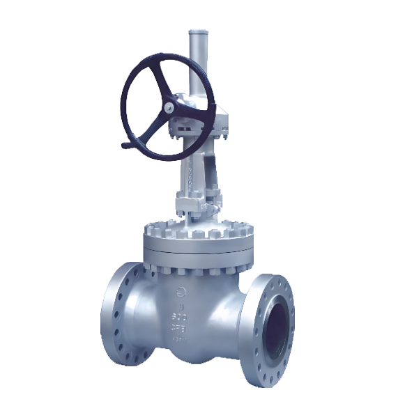 API Standard Bevel Gear Gate Valve
Model:
Z541H-150LB/Z541H-300LB/Z541H-600LB/Z541H-900LB/Z541Y-150LB/Z541Y-300LB/Z541Y-600LB/Z541Y-900LB/Specification:
1-1/2’’-48’’Pressure:
class150-class2500Material:
cast steel, stainless steel -
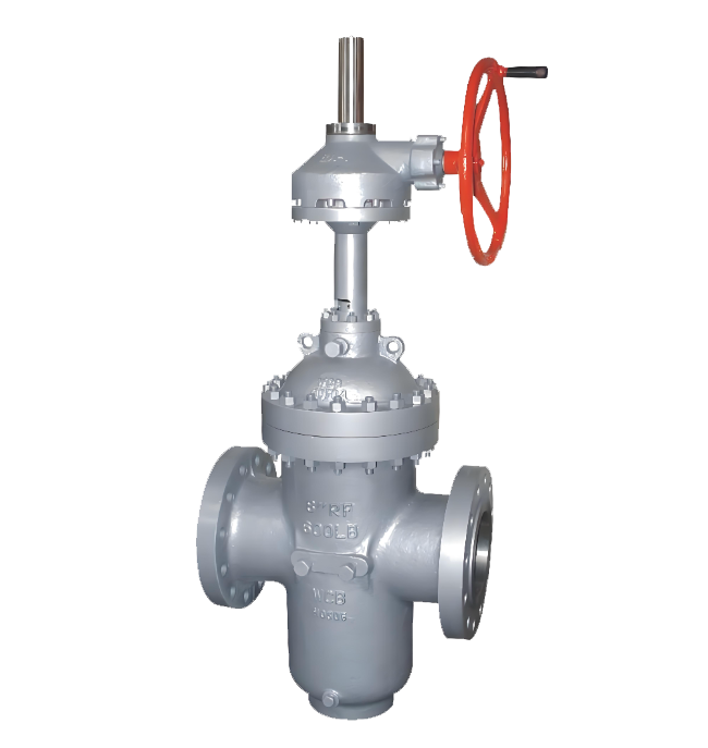 Z543Y flat gate valve
Model:
Z543Y-16C/Z543Y-25C/Z543Y-40C/Z543Y-64C/Z543Y-16P/Z543Y-25P/Z543Y-40P/Z543Y-64P/Z543Y-16R/Z543Y-25R/Z543Y-40R/Z543Y-64RSpecification:
DN50-DN600Pressure:
PN16-PN64Material:
Cast steel, stainless steel
What are the structural characteristics of knife gate valves? A detailed explanation of their six major advantages and application areas
Description: This article provides a detailed analysis of the unique structure, six core characteristics, and working principle of knife gate valves. It explains how they achieve automatic control through accessories and are widely used in industries such as chemical, paper, and wastewater treatment. They are ideal sealing and throttling valves.
Text:
The knife gate valve, as a high-performance industrial valve, is widely used in various fields such as chemical industry, coal, sugar manufacturing, sewage, paper making, etc., due to its unique structure and excellent performance. It is particularly suitable for regulating, throttling, and cutting off media in pipelines. This article will provide an in-depth analysis of the structural composition and core characteristics of the knife gate valve.
I. Basic Structure and Working Principle of Knife Gate Valve The knife gate valve is primarily composed of left/right valve bodies, U-shaped sealing rings, gate plates, valve stems, brackets, and driving devices (such as cylinders). Its core opening and closing actions are typically driven by cylinders. With supporting accessories such as solenoid valves and proximity switches, it can easily achieve on-off control, signal feedback, or continuous automatic adjustment, demonstrating a high degree of automation integration.
II. Six Core Structural Features of Knife Gate Valves The excellent performance of knife gate valves stems from their carefully designed structure, which is mainly reflected in the following six aspects:
The wafer-style design is compact and lightweight. Utilizing an advanced wafer-style connection structure, it significantly reduces the volume and weight compared to traditional flange valves, saving installation space and reducing the load on the pipeline system.
The full-bore flow passage provides a completely open straight-through channel when the non-clogging valve is opened, allowing the medium to pass through unimpeded. This design effectively prevents the deposition and clogging of media such as slurry and particles within the valve body, making it particularly suitable for applications involving fibers or solid particles, such as in paper making and wastewater treatment.
U-shaped seal ring, excellent sealing performance. A specially designed elastic U-shaped seal ring is used as the main seal, which can adaptively compensate for wear, ensuring that the valve maintains good bidirectional sealing performance and low leakage rate even after long-term use.
The elastic valve seat facilitates the maintenance of the gate plate's external seal, which is achieved by an elastic sealing strip embedded in the valve body. This sealing strip can be adjusted or quickly replaced using screws and a pressure plate, making maintenance simple and greatly extending the service life of the valve while reducing maintenance costs.
Streamlined design ensures minimal flow resistance. Due to the straight and smooth channels, as well as the thin and sharp gate plate (shaped like a blade), the flow resistance experienced by the medium is negligible, contributing to a reduction in system energy consumption.
Modular structure, convenient for installation and maintenance. The overall structure is designed to be simple and highly modular, making installation, disassembly, and routine maintenance very convenient, significantly reducing downtime for maintenance.
III. Summary of Application Scenarios Due to its prominent features of anti-clogging, easy adjustment, good sealing, and low flow resistance, the knife gate valve has become an ideal choice for handling harsh working conditions such as viscous media, slurry, dust mixtures, and sewage. It plays an irreplaceable key role in pulp adjustment in the paper industry, material liquid transportation in the chemical industry, emission control in sewage treatment plants, and solid material pipelines in industries such as coal and sugar manufacturing.
In summary, the knife gate valve is a valve solution that highly combines practicality, reliability, and economy. Its innovative structural design directly addresses common pain points in industrial applications, making it an indispensable and important component in modern process industry pipeline systems.
Rewriting instructions:
Enhance title and keyword layout: Optimize the title according to SEO requirements, extract core keywords such as "structural features", "advantages", and "application areas", and distribute them reasonably.
Optimize content structure and hierarchy: Adjust the segmentation of the original text, adopt hierarchical headings and bullet points, and enhance the coherence and readability of the information.
Supplementary induction and summary of applicable scenarios: Add a summary paragraph to highlight the comprehensive value of the product, enhancing the depth of content and user reference value.
If you prefer a more lively or technical document style, I can continue to optimize and adjust it for you.
Address:No. 1, Linxia Road, Sanqiao Industrial Zone, Oubei Sub-district, Yongjia County, Zhejiang Province| Switchboard:0577-67198981| mobile:+8613388552747| Email:sales@shanliuvalve.com|
COPYRIGHT © Zhejiang Shanliu Valve Technology Co., Ltd. Main Business: Water Valve Industrial valve|
浙ICP备2026020749号![]()