Your location:
 /
valves
/
Gate Valve
/
hard seal gate valve
/
Z41H Forged Steel Flanged Gate Valve
/
valves
/
Gate Valve
/
hard seal gate valve
/
Z41H Forged Steel Flanged Gate Valve

Mark Classification of Fluid products
- Phone:+86(577)67198981
- Fax:+86(577)67038872
- mobile:+8613388552747
- Sales Email 1:Karrie@shanliuvalve.com
- Sales Email 2:Yannie@shanliuvalve.com
- Sales Email 3:Merry@shanliuvalve.com
- Sales Email 4:Lucas@shanliuvalve.com
- Email:sales@shanliuvalve.com

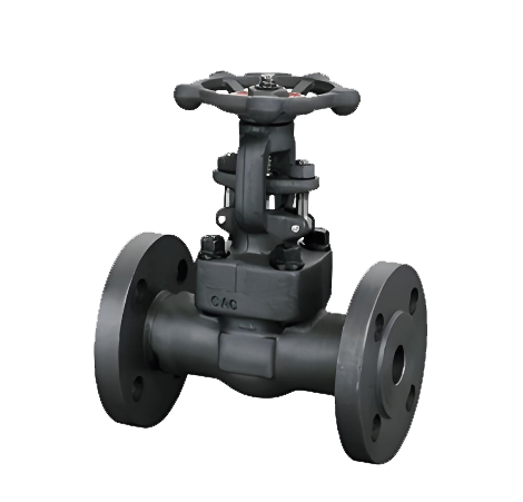
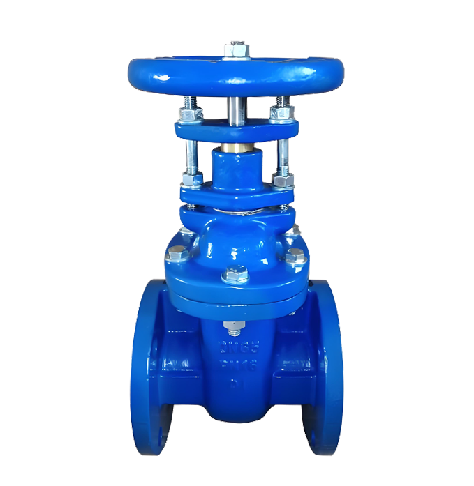
Z41H Forged Steel Flanged Gate Valve
- Model:Z41H-16C/Z41H-25C/Z41H-40C/Z41H-64C/Z41H-100C//Z41H-160C//Z41H-320C/Z41H-16P/Z41H-25P/Z41H-40P/Z41H-64P/Z41H-100P//Z41H-160P//Z41H-320P/Z41H-16R/Z41H-25R/Z41H-40R/Z41H-64R/Z41H-100R//Z41H-160R//Z41H-320R
- Specification:DN15~DN65
- Temperature:-110℃~560℃
- Medium:water, oil, steam, gas, and corrosive media.
- Pressure:PN16~PN320
- Connection method:flange
- Driving method:manual
- Material: forged steel, forged stainless steel


Add QR code to serve you!
- Product Overview
- Performance Data
- Size Weight
Z41H forged steel flange gate valve is a rising stem wedge gate valve manufactured with forged steel valve body and flange connection. The valve body is formed through forging process, with a dense internal structure and better mechanical properties than castings. The valve is driven by a handwheel to lift and lower the valve stem, which in turn drives the wedge gate to open and close the pipeline. The sealing surface adopts alloy steel overlay welding ("H" type) to form a metal hard seal. This valve is designed specifically for high pressure, high temperature, and critical working conditions, with higher strength, toughness, and reliability, making it an ideal choice for demanding pipelines in industries such as petroleum, chemical, and power. Widely used in petrochemical plants, refineries, power plant boiler feedwater systems, high-pressure steam pipelines, natural gas gathering and transportation pipelines, and high-temperature and high-pressure process pipelines with strict requirements for valve strength, sealing, and durability, as a key cutoff equipment.
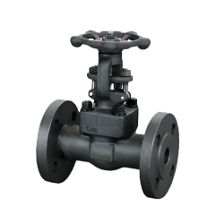
Z41H Forged Steel Flanged Gate Valve Product Drawing
Characteristic
1. Forged steel valve body, high strength
The valve body is forged from high-quality forged steel (such as A105, F304, F316), with a dense structure, no casting defects, high mechanical strength, and good impact resistance, suitable for high pressure and fatigue conditions.
2. Clear stem structure, intuitive valve position
The valve stem rises and falls with the gate, and the valve opening can be directly determined by observing the height of the valve stem extension, which is convenient for operation and maintenance.
3. Alloy steel hard seal ("H" type)
The sealing surface of the valve disc and seat is welded with hard alloy (such as 13Cr, Stellite), which has high hardness, wear resistance, erosion resistance, high temperature resistance, reliable sealing, and long service life.
4. Flange connection, stable and reliable
Using standard flange connections (such as RF, RTJ), the connection strength is high, the sealing performance is good, and it is easy to install and disassemble.
5. Suitable for high temperature and high pressure working conditions
The overall structure and material selection make it suitable for higher working pressures (such as PN16-PN100) and temperatures (-29 ℃~425 ℃), with stable performance.
6 full bore design, low flow resistance
Adopting a full bore flow channel, the medium has low flow resistance and pressure loss, making it suitable for systems with pressure drop requirements

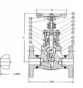
Z41H Forged Steel Flanged Gate Valve Structure Diagram
Part name and material list
| 序号No | 零件名称Part name | CS to ASTM | A5 to ASTM | SS to ASTM |
| Type A105 | Type F22 | Type F304(L) | ||
| 1 | 阀体Body | A105 | A182 F22 | A182 F304(L) |
| 2 | 阀座seat | A276 420 | A276 304 | A276 304(L) |
| 3 | 闸板plate | A276 4308&410 | A182 F304 | A182 F304(L) |
| 4 | 阀杆stem | A182 F6 | A182 F304 | A182 F304(L) |
| 5 | 垫片Gasket | 304夹柔性石墨 | 304+PTFE | |
| 6 | 阀盖cover | A105 | A182 F22 | A182 F304(L) |
| 7 | 螺栓 Bolt | A193 B7 | A193 B16 | A193 B8 |
| 8 | 钳子Pliers | A276 420 | A182 F304 | |
| 9 | 填料压盖Gland packing | A276 410 | A182 F304(L) | |
| 10 | 螺栓Bolt | A193 B7 | A193 B16 | A193 B8 |
| 11 | 填料压板Filler pressure plate | A105 | A182 F11 | A182 F304(L) |
| 12 | 螺母nut | A194 2H | A194 4 | A194 8 |
| 13 | 阀杆螺母Stem nut | A276 420 | ||
| 14 | 螺母Nut | A194 2H | A194 4 | A194 8 |
| 16 | 手轮hand wheel | A197 | ||
| 17 | 垫片Gasket | A473 431 | ||
| 18 | 填料Filler | 柔性石墨Flexible graphite | PTFE |
Performance Specification Sheet
| 性能规范表 Performance Specification Sheet | ||
| 公称压力 Nominal pressure | 25 | MPa |
| 强度试验压力 Strength test pressure | 37.5 | |
| 密封试验压力Seal test pressure | 27.5 | |
| 适用温度 Applicable temperature | -110 and ≤260 | ℃ |
Outline Drawing of Z41H Forged Steel Flanged Gate Valve
Outline Dimension Table
| 规格model | 1/2" | 3/4" | 1" | 1/4" | 1-1/2" | 2" | ||
| L(RF)L1(BW) | 150 | 108 | 117 | 127 | 140 | 165 | 203 | |
| 300 | 140 | 152 | 165 | 178 | 190 | 216 | ||
| 600 | 165 | 190 | 216 | 229 | 241 | 292 | ||
| H(开) | 150,300 | 158 | 169 | 197 | 236 | 246 | 283 | |
| 600 | 169 | 197 | 236 | 246 | 283 | 320 | ||
| W | 100 | 100 | 125 | 160 | 160 | 180 | ||
| 重量weight | 150 | RF | 4.5 | 5.2 | 8.2 | 11.5 | 12.5 | 20.3 |
| BW | 2.8 | 3.3 | 5.4 | 7.1 | 8.2 | 12.5 | ||
| 300 | RF | 4.8 | 6.2 | 9.3 | 14 | 15.5 | 23.4 | |
| BW | 3.5 | 4.4 | 6.8 | 8.1 | 9.2 | 15.4 | ||
| 600 | RF | 5.9 | 7.4 | 10.4 | 16.2 | 17.5 | 28.3 | |
| BW | 4.5 | 5.1 | 8.2 | 10.5 | 12.4 | 20.1 |
-
 DIN Standard Metal-Seated Gate Valve
Model:
Z41H-10Q/Z41H-16Q/Z41H-25Q/Z41H-10C/Z41H-16C/Z41H-25C/Z41H-10P/Z41H-16P/Z41H-25PSpecification:
DN15-DN600Pressure:
PN10-PN25Material:
ductile iron, cast steel, stainless steel -
 BS Standard Non-Rising Stem Metal-Seated Gate Valve
Model:
Z41T-150LB/Z41T-300LB/Z41T-600LB/Z41H-150LB/Z41H-300LB/Z41H-600LBSpecification:
Z41T-150LB/Z41T-300LB/Z41T-600LB/Z41H-150LB/Z41H-300LB/Z41H-600LBPressure:
150LB-600LBMaterial:
ductile iron, cast steel, stainless steel -
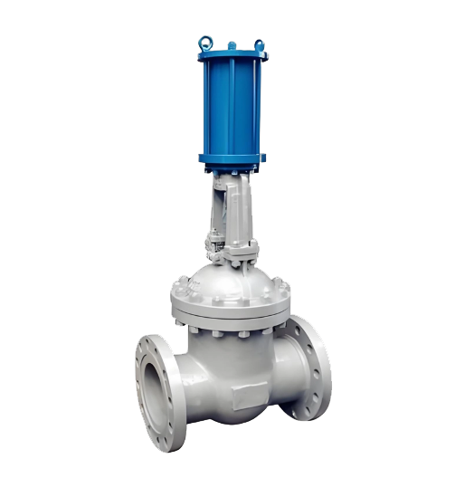 Z741H Hydraulic Flanged Gate Valve
Model:
Z741H-16C/Z741H-25C/Z741H-40C/Z741H-64C/Z741H-16P/Z741H-25P/Z741H-40P/Z741H-64P/Z741H-16R/Z741H-25R/Z741H-40R/Z741H-64RSpecification:
DN50-DN300Pressure:
PN16-PN64Material:
cast steel, stainless steel

What are the structural characteristics of knife gate valves? A detailed explanation of their six major advantages and application areas
Description: This article provides a detailed analysis of the unique structure, six core characteristics, and working principle of knife gate valves. It explains how they achieve automatic control through accessories and are widely used in industries such as chemical, paper, and wastewater treatment. They are ideal sealing and throttling valves.
Text:
The knife gate valve, as a high-performance industrial valve, is widely used in various fields such as chemical industry, coal, sugar manufacturing, sewage, paper making, etc., due to its unique structure and excellent performance. It is particularly suitable for regulating, throttling, and cutting off media in pipelines. This article will provide an in-depth analysis of the structural composition and core characteristics of the knife gate valve.
I. Basic Structure and Working Principle of Knife Gate Valve The knife gate valve is primarily composed of left/right valve bodies, U-shaped sealing rings, gate plates, valve stems, brackets, and driving devices (such as cylinders). Its core opening and closing actions are typically driven by cylinders. With supporting accessories such as solenoid valves and proximity switches, it can easily achieve on-off control, signal feedback, or continuous automatic adjustment, demonstrating a high degree of automation integration.
II. Six Core Structural Features of Knife Gate Valves The excellent performance of knife gate valves stems from their carefully designed structure, which is mainly reflected in the following six aspects:
The wafer-style design is compact and lightweight. Utilizing an advanced wafer-style connection structure, it significantly reduces the volume and weight compared to traditional flange valves, saving installation space and reducing the load on the pipeline system.
The full-bore flow passage provides a completely open straight-through channel when the non-clogging valve is opened, allowing the medium to pass through unimpeded. This design effectively prevents the deposition and clogging of media such as slurry and particles within the valve body, making it particularly suitable for applications involving fibers or solid particles, such as in paper making and wastewater treatment.
U-shaped seal ring, excellent sealing performance. A specially designed elastic U-shaped seal ring is used as the main seal, which can adaptively compensate for wear, ensuring that the valve maintains good bidirectional sealing performance and low leakage rate even after long-term use.
The elastic valve seat facilitates the maintenance of the gate plate's external seal, which is achieved by an elastic sealing strip embedded in the valve body. This sealing strip can be adjusted or quickly replaced using screws and a pressure plate, making maintenance simple and greatly extending the service life of the valve while reducing maintenance costs.
Streamlined design ensures minimal flow resistance. Due to the straight and smooth channels, as well as the thin and sharp gate plate (shaped like a blade), the flow resistance experienced by the medium is negligible, contributing to a reduction in system energy consumption.
Modular structure, convenient for installation and maintenance. The overall structure is designed to be simple and highly modular, making installation, disassembly, and routine maintenance very convenient, significantly reducing downtime for maintenance.
III. Summary of Application Scenarios Due to its prominent features of anti-clogging, easy adjustment, good sealing, and low flow resistance, the knife gate valve has become an ideal choice for handling harsh working conditions such as viscous media, slurry, dust mixtures, and sewage. It plays an irreplaceable key role in pulp adjustment in the paper industry, material liquid transportation in the chemical industry, emission control in sewage treatment plants, and solid material pipelines in industries such as coal and sugar manufacturing.
In summary, the knife gate valve is a valve solution that highly combines practicality, reliability, and economy. Its innovative structural design directly addresses common pain points in industrial applications, making it an indispensable and important component in modern process industry pipeline systems.
Rewriting instructions:
Enhance title and keyword layout: Optimize the title according to SEO requirements, extract core keywords such as "structural features", "advantages", and "application areas", and distribute them reasonably.
Optimize content structure and hierarchy: Adjust the segmentation of the original text, adopt hierarchical headings and bullet points, and enhance the coherence and readability of the information.
Supplementary induction and summary of applicable scenarios: Add a summary paragraph to highlight the comprehensive value of the product, enhancing the depth of content and user reference value.
If you prefer a more lively or technical document style, I can continue to optimize and adjust it for you.
Address:No. 1, Linxia Road, Sanqiao Industrial Zone, Oubei Sub-district, Yongjia County, Zhejiang Province| Switchboard:0577-67198981| mobile:+8613388552747| Email:sales@shanliuvalve.com|
COPYRIGHT © Zhejiang Shanliu Valve Technology Co., Ltd. Main Business: Water Valve Industrial valve|
浙ICP备2026020749号![]()