Your location:
 /
valves
/
industrial valve
/
Globe valve
/
U41S Plunger Stop Valve
/
valves
/
industrial valve
/
Globe valve
/
U41S Plunger Stop Valve

Mark Classification of Fluid products
- Phone:+86(577)67198981
- Fax:+86(577)67038872
- mobile:+8613388552747
- Sales Email 1:Karrie@shanliuvalve.com
- Sales Email 2:Yannie@shanliuvalve.com
- Sales Email 3:Merry@shanliuvalve.com
- Sales Email 4:Lucas@shanliuvalve.com
- Email:sales@shanliuvalve.com

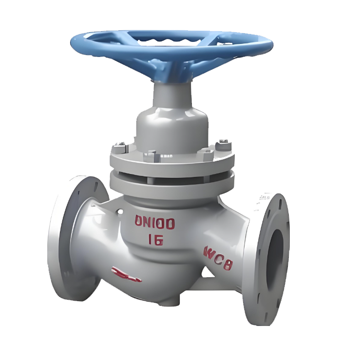
U41S Plunger Stop Valve
- Model:U41S-16C/U41S-25C/U41S-40C/U41S-16P/U41S-25P/U41S-40P/U41S-16R/U41S-25R/U41S-40R
- Specification:DN15-DN400
- Temperature:≤ 425 ℃
- Medium:Water, steam, oil and similar liquids and gases
- Pressure:PN16~PN40
- Connection method:flange
- Driving method:Handwheel
- Material:Cast steel, stainless steel


Add QR code to serve you!
- Product Overview
- Performance Data
- Size Weight
Overview
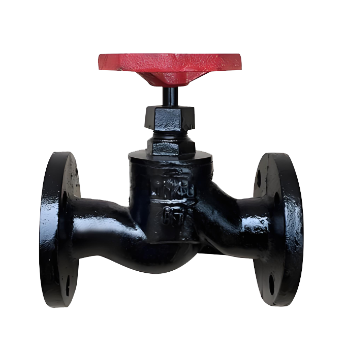
The U41S Plunger Stop Valve is a special structure stop valve that achieves reliable sealing through the interference fit between the plunger and the sealing ring. Driven by the valve stem, the plunger performs vertical lifting motion within the sealing ring to complete the opening/closing and flow regulation of the pipeline medium. The core of its design lies in replacing the traditional disc with a plunger. The interference fit design between the plunger and the upper and lower elastic sealing rings, combined with the pre-tightening force adjustment of the middle flange bolts, causes the side force generated by the compression of the sealing rings to act on the outer cylindrical surface of the plunger and the bore surface of the valve body. This forms a reliable radial sealing pair, thereby achieving excellent zero-leakage sealing performance. The key components of the valve feature a stainless steel plunger and high-performance non-metallic sealing rings (such as flexible graphite, PTFE composite materials, etc.). The sealing rings possess characteristics of strong resilience, high wear resistance, and high-temperature resistance, maintaining elasticity and sealing performance during long-term use. The valve typically adopts a flanged connection, securely fixed to the pipeline flanges with bolts, offering convenient installation and reliable sealing. The opening and closing of the valve are achieved by turning the handwheel or a matching electric actuator to drive the valve stem, converting rotary motion into the vertical lifting motion of the plunger for smooth and reliable control. This valve combines the leak-free advantages of plunger valves with the quick opening/closing characteristics of stop valves. It is widely used in process pipeline systems in industries such as petroleum, chemical, electric power, metallurgy, pharmaceutical, and heating supply, especially suitable for working conditions involving steam, oil, water, and generally corrosive media where strict sealing performance and frequent operation are required.

U41S Plunger Stop Valve Product Drawing
Features
1.Zero-Leakage Sealing Structure: Utilizes a unique interference fit design between the plunger and elastic sealing rings. By adjusting the pre-tightening force of the middle flange bolts, the sealing rings are radially compressed, forming a reliable radial sealing pair on the outer surface of the plunger. This completely replaces the traditional flat sealing structure of stop valves, achieving excellent zero-leakage sealing performance, particularly suitable for steam, oil, and working conditions with strict leakage control requirements.
2.Long-Life Sealing Components: The sealing rings are made of flexible graphite, PTFE, and high-elasticity composite materials, offering excellent high-temperature stability, self-lubrication, and resilience. They maintain sealing performance without degradation during long-term frequent operation. The plunger is precision-polished to a high surface finish, forming a beneficial friction pair with the sealing rings, significantly extending the valve's service life.
3.Adaptability to Harsh Conditions: The plunger is made of stainless steel, providing good corrosion resistance and anti-erosion capability. Sealing ring materials can be flexibly selected based on working conditions—flexible graphite for high-temperature steam, PTFE for highly corrosive media—ensuring long-term stable operation of the valve in high-temperature, high-pressure, and corrosive environments.
4.Self-Cleaning and Anti-Seizing: The radial sealing structure between the plunger and sealing rings creates a wiping action during opening and closing, automatically removing impurities and scale accumulated on the plunger surface, preventing particle seizing on the sealing surface. Additionally, the reciprocating vertical motion of the plunger ensures uniform wear of the sealing rings, avoiding sealing failure caused by localized excessive wear.
5.Easy Operation and Quick Opening/Closing: The plunger has a short vertical lifting stroke, significantly reducing the number of operating turns compared to traditional stop valves. The precise valve stem guide structure ensures smooth movement and low operating torque, making it suitable for applications requiring frequent operation. It can be equipped with handwheels, electric actuators, or pneumatic actuators to meet various automation control requirements.
6.Compact Structure and Convenient Maintenance: Features a flanged connection conforming to national standards for easy installation. The sealing rings are independent, replaceable components. During maintenance, the entire valve does not need disassembly; simply opening the bonnet allows for replacement of the sealing components, resulting in low maintenance costs and minimal downtime. The valve body flow path is smoothly designed for low medium flow resistance, offering significant energy-saving effects.
7.Wide Applicability: Suitable for water, steam, oil, gases, and various corrosive media. Widely used in process pipelines in petroleum, chemical, electric power, metallurgy, pharmaceutical, and heating systems, especially suitable for steam pipelines and thermal oil systems requiring frequent operation and stringent sealing performance. It is an ideal shut-off and control element in modern industrial piping systems.

U41S Plunger Stop Valve Structure Diagram
Main Parts Materials
| 名称 Name | 材料 Material |
| 阀体、阀盖 Valve Body & Bonnet | 铸钢、不锈钢 Cast Steel, Stainless Steel |
| 阀杆 Valve Stem | 碳钢 Carbon Steel |
| 柱塞 Plunger | 不锈钢 Stainless Steel |
| 密封圈 Seal Ring | 聚四氟乙烯(PTFE) Polytetrafluoroethylene (PTFE) |
| 手轮 Handwheel | 铸铁 Cast Iron |
Performance Specification Table
| 性能规范表Performance Specification Table | ||
| 公称压力Nominal Pressure | 1.6/2.5/4.0 | MPa |
| 强度试验压力Strength Test Pressure | 2.4/3.75/6 | |
| 密封试验压力Seal Test Pressure | 1.76/2.75/4.4 | |
| 适用温度Applicable Temperature | 1.6/2.5/4.0 | ℃ |
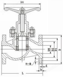
Outline Dimension Drawing of U41S Plunger Stop Valve
Outline Dimension Table of U41S Plunger Stop Valve
| DN(mm) 尺寸Dimensions(mm) | U41SM-16C、P、R | |||||||||||||||
| 15 | 20 | 25 | 32 | 40 | 50 | 65 | 80 | 100 | 125 | 150 | 200 | 250 | 300 | 350 | 400 | |
| L | 130 | 150 | 160 | 180 | 200 | 230 | 290 | 310 | 350 | 400 | 480 | 495 | 622 | 698 | 787 | 914 |
| H | 170 | 190 | 200 | 230 | 260 | 280 | 300 | 370 | 400 | 420 | 510 | 590 | 710 | 830 | 950 | 1080 |
| W | 100 | 100 | 120 | 140 | 160 | 180 | 200 | 240 | 270 | 310 | 340 | 400 | 520 | 640 | 760 | 900 |
| D | 95 | 105 | 115 | 135 | 145 | 160 | 180 | 195 | 215 | 245 | 280 | 335 | 405 | 460 | 520 | 580 |
| K | 65 | 75 | 85 | 100 | 110 | 125 | 145 | 160 | 180 | 210 | 240 | 295 | 355 | 410 | 470 | 525 |
| D1 | 45 | 55 | 65 | 78 | 85 | 100 | 120 | 135 | 155 | 185 | 210 | 265 | 320 | 375 | 435 | 485 |
| t | 14 | 14 | 14 | 16 | 16 | 16 | 18 | 20 | 20 | 22 | 24 | 26 | 30 | 30 | 34 | 36 |
| n-q | 4-14 | 4-14 | 4-18 | 4-18 | 4-18 | 4-18 | 4-18 | 8-18 | 8-18 | 8-18 | 8-23 | 12-23 | 12-25 | 12-25 | 16-25 | 16-30 |
| 重量 Weight(千克) | 3.5 | 4.5 | 5.5 | 8 | 11.5 | 15 | 21 | 30 | 42 | 55 | 90 | 142 | 210 | 290 | 500 | |
| DN(mm) 尺寸Dimensions(mm) | U41SM-25C、P、R | |||||||||||||||
| 15 | 20 | 25 | 32 | 40 | 50 | 65 | 80 | 100 | 125 | 150 | 200 | 250 | 300 | 350 | 400 | |
| L | 130 | 150 | 160 | 180 | 200 | 230 | 290 | 310 | 350 | 400 | 480 | 533 | 622 | 711 | 838 | 914 |
| H | 170 | 190 | 210 | 240 | 240 | 270 | 300 | 350 | 400 | 440 | 510 | 590 | 710 | 830 | 950 | 1080 |
| W | 100 | 100 | 110 | 140 | 160 | 180 | 200 | 240 | 270 | 310 | 330 | 400 | 520 | 640 | 760 | 900 |
| D | 95 | 105 | 115 | 135 | 145 | 160 | 180 | 195 | 230 | 270 | 300 | 360 | 425 | 485 | 550 | 610 |
| K | 65 | 75 | 85 | 100 | 110 | 125 | 145 | 160 | 190 | 220 | 250 | 310 | 370 | 430 | 490 | 550 |
| D1 | 45 | 55 | 65 | 78 | 85 | 100 | 120 | 135 | 160 | 188 | 218 | 278 | 332 | 390 | 448 | 505 |
| t | 16 | 16 | 16 | 18 | 18 | 20 | 22 | 22 | 24 | 28 | 30 | 34 | 36 | 40 | 44 | 48 |
| n-φ | 4-14 | 4-14 | 4-14 | 4-18 | 4-18 | 4-18 | 8-18 | 8-18 | 8-23 | 8-25 | 8-25 | 12-25 | 12-30 | 16-30 | 16-34 | 16-34 |
| 重量Weight(千克) | 3.5 | 4.5 | 5.5 | 8 | 11.5 | 15 | 21 | 30 | 42.5 | 57 | 91 | 150 | 220 | 300 | 550 | |
| DN(mm) 尺寸Dimensions(mm) | U41SM-40C、P、R | |||||||||||||||
| 15 | 20 | 25 | 32 | 40 | 50 | 65 | 80 | 100 | 125 | 150 | 200 | 250 | 300 | 350 | 400 | |
| L | 130 | 150 | 160 | 180 | 200 | 230 | 290 | 310 | 350 | 400 | 480 | 495 | 622 | 698 | 787 | 914 |
| H | 170 | 190 | 200 | 230 | 260 | 280 | 300 | 370 | 400 | 420 | 510 | 590 | 710 | 830 | 950 | 1080 |
| W | 100 | 100 | 120 | 140 | 160 | 180 | 200 | 240 | 270 | 310 | 340 | 400 | 520 | 540 | 780 | 900 |
| D | 95 | 105 | 115 | 135 | 145 | 160 | 180 | 195 | 230 | 270 | 300 | 375 | 445 | 510 | 570 | 655 |
| K | 65 | 75 | 85 | 100 | 110 | 125 | 145 | 160 | 190 | 220 | 250 | 320 | 385 | 450 | 510 | 585 |
| D1 | 39 | 50 | 57 | 65 | 75 | 87 | 109 | 120 | 149 | 175 | 203 | 259 | 312 | 363 | 421 | 473 |
| t | 16 | 16 | 16 | 18 | 18 | 20 | 22 | 22 | 24 | 28 | 30 | 38 | 42 | 46 | 52 | 58 |
| n-9 | 4-14 | 4-14 | 4-14 | 4-18 | 4-18 | 4-18 | 4-18 | 8-18 | 8-23 | 8-25 | 8-25 | 12-30 | 12-34 | 16-34 | 16-34 | 16-41 |
-
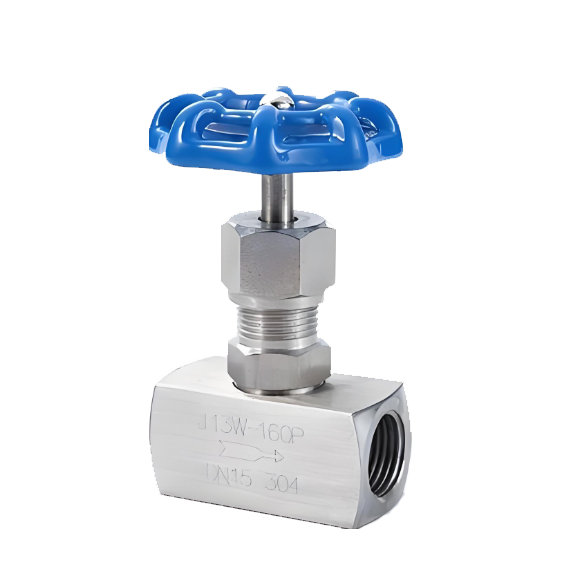 J13W needle type internal thread globe valve
Model:
J13W-25C/J13W-40C/J13W-64C/J13W-100C/J13W-160C/J13W-320C/J13W-25P/J13W-40P/J13W-64P/J13W-100P/J13W-160P/J13W-320P/J13W-25R/J13W-40R/J13W-64R/J13W-100R/J13W-160R/J13W-320RSpecification:
DN6-DN25Pressure:
PN25~PN320Material:
Forged steel, forged stainless steel -
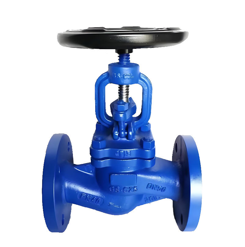 DIN Standard Globe Valve
Model:
J41W-16Q/J41W-25Q/J41W-16C/J41W-25C/J41W-16P/J41W-25PSpecification:
DN15-DN300Pressure:
PN16-PN25Material:
Cast iron, cast steel, stainless steel -
 J41T Cast Iron Flanged Stop Valve
Model:
J41T-10/J41T-16Specification:
DN15-DN200Pressure:
PN10-PN16Material:
Cast iron
Address:No. 1, Linxia Road, Sanqiao Industrial Zone, Oubei Sub-district, Yongjia County, Zhejiang Province| Switchboard:0577-67198981| mobile:+8613388552747| Email:sales@shanliuvalve.com|
COPYRIGHT © Zhejiang Shanliu Valve Technology Co., Ltd. Main Business: Water Valve Industrial valve|
浙ICP备2026020749号![]()