Your location:
 /
valves
/
Gate Valve
/
Knife Gate Valve
/
PZ673 Pneumatic Wafer Knife Gate Valve
/
valves
/
Gate Valve
/
Knife Gate Valve
/
PZ673 Pneumatic Wafer Knife Gate Valve

Mark Classification of Fluid products
- Phone:+86(577)67198981
- Fax:+86(577)67038872
- mobile:+8613388552747
- Sales Email 1:Karrie@shanliuvalve.com
- Sales Email 2:Yannie@shanliuvalve.com
- Sales Email 3:Merry@shanliuvalve.com
- Sales Email 4:Lucas@shanliuvalve.com
- Email:sales@shanliuvalve.com

PZ673 Pneumatic Wafer Knife Gate Valve
- Model:PZ673H-10C/PZ673H-16C/PZ673X-6C/PZ673X-10C/PZ673F-6C/PZ673F-10C/PZ673F-16C/PZ673H-10P/PZ673H-16P/PZ673X-6P/PZ673X-10P/PZ673F-6P/PZ673F-10P/PZ673F-16P
- Specification:DN50~1200
- Temperature:-40~450℃
- Medium:Slurry, pulp, sewage, and applications requiring rapid shut-off
- Pressure:0.6~1.6MPa
- Connection method:Wafer
- Driving method:Pneumatic
- Material:Carbon steel, stainless steel


Add QR code to serve you!
- Product Overview
- Performance Data
- Size Weight
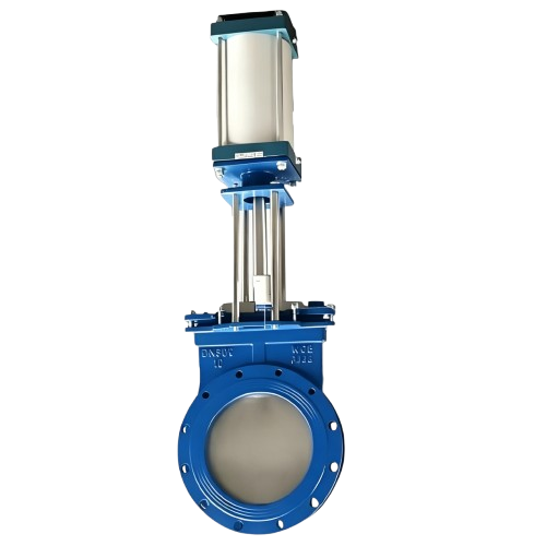
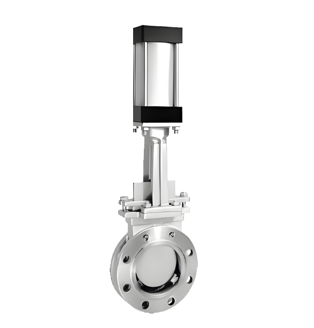
PZ673 Pneumatic Wafer Knife Gate Valve is an industrial automation execution unit combining a pneumatic actuator with an ultra-thin knife gate valve body. Utilizing compressed air as the power source, the pneumatic cylinder drives the piston to move the gate plate in a linear reciprocating motion, thereby opening or closing the pipeline. The core design features a gate plate with a sharp knife-edge at the bottom, which effectively shears through fibers, paper pulp, wood pulp, and impurities at the moment of closing to prevent jamming. The letters H, X, and F represent metal hard seal, rubber soft seal, and fluoroplastic seal, respectively, to meet various temperature, pressure, and corrosive conditions. Known for its short face-to-face dimension, light weight, and low flow resistance, this valve is widely used in paper making, mining, coal washing, chemicals, and sewage treatment systems.
Product Image of PZ673 Pneumatic Wafer Knife Gate Valve
Feature
1. Ultra-short structure saves space:The wafer-style thin design ensures overall dimensions and weight are significantly lower than traditional gate valves. This saves installation space and reduces mechanical loads on the pipeline system, lowering support costs.
2.Knife-edge gate for powerful shearing:The bottom of the gate is precision-machined into a wedge-shaped edge. It provides a strong shearing effect during closing, easily cutting through impurities and fibers in viscous media to eliminate the risk of sticking or incomplete closure.
3.Full-bore design and low resistance:When fully open, the flow area matches the pipe diameter exactly, resulting in an extremely low resistance coefficient. This structure prevents media deposition and significantly reduces pumping energy consumption.
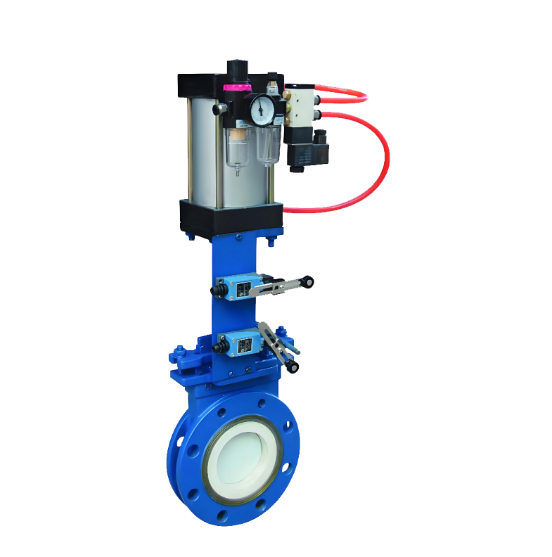
4.Powerful and stable pneumatic drive:Equipped with high-performance pneumatic cylinders, providing large output thrust and rapid response. It can be configured with solenoid valves and limit switches for remote control and supports fail-safe pre-setting.
5.Diverse sealing configurations:Available in H (metal seat for heat/wear resistance), X (rubber for tight seal), and F (PTFE for anti-corrosion) materials. The scientific seat design ensures reliable performance in both pressure directions.
6.Durable internal materials:Body and internals are available in cast steel, stainless steel, or wear-resistant alloys. The gate surface is typically hard-chrome plated or nitrided to enhance hardness and erosion resistance for long-term stability.
7.Modular design for easy service:The simple structure features minimal wearing parts. Actuator-to-body connections are standardized, allowing for online inspection and replacement of packing and seals without removing the valve from the line.
8.Intrinsic safety and protection:Driven by compressed air, it eliminates spark risks, providing natural safety for hazardous zones such as powder-dense, flammable, or explosive industrial environments.
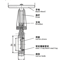
Structural Drawing of PZ673 Pneumatic Wafer Knife Gate Valve
List of Component Names and Materials
| Part Name | Material Name | Material Grade/Mark |
| Round Nut | High-quality Carbon Steel | 25 |
| Handwheel | Grey Cast Iron | HT200 |
| Bearing Gland | High-quality Carbon Steel | 35 |
| Stem Nut | Aluminum Bronze / Aluminum Brass | ZCuAl9Mn2... / ZCuZn25Al6Fe3Mn3 |
| Bearing | — | 51110 |
| Stem | Stainless Steel | 304, 316, 2Cr13 |
| Yoke / Bracket | Carbon Steel, Stainless Steel | WCB, CF8, etc. |
| Wedge / Disc | Stainless Steel | 304, 316, 304L, 316L, 2Cr13 |
| Bolt and Nut | High-quality Carbon Steel | 35 |
| Packing Gland | Carbon Steel | WCB |
| Packing | Flexible Graphite, PTFE Fiber, etc. | — |
| Valve Body | Carbon Steel, Stainless Steel | WCB, CF8, CF3, CF8M, CF3M, etc. |
Performance Specification Sheet
| Performance Specification Sheet | ||||
| Nominal Pressure | 0.6 | 1.0 | 1.6 | MPa |
| Strength test pressure | 0.9 | 1.5 | 2.4 | |
| Sealing test pressure | 0.66 | 1.1 | 1.76 | |
| Applicable Temperature | -40-450 | ℃ | ||
Standard requirements for external dimensions
1.Design & Manufacture: JB/T869l-1998 MSS SP-81
2.Flange Dimensions:GB/T9113.1-2000
3.Face-to-Face Dimensions:GB/T1-5188.2-94
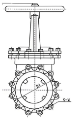
Outline Drawing of PZ673 Pneumatic Wafer Knife Gate Valve
Outline dimension table(Unit:mm)
| MPa | DN | L | D | D1 | D2 | H | N-M | A |
| 1.0 | 50 | 43 | 160 | 125 | 100 | 330 | 4-M16 | 180 |
| 65 | 46 | 180 | 145 | 120 | 360 | 4-M16 | 180 | |
| 80 | 46 | 195 | 160 | 135 | 390 | 4-M16 | 220 | |
| 100 | 52 | 215 | 180 | 155 | 440 | 8-M16 | 220 | |
| 125 | 56 | 245 | 210 | 185 | 510 | 8-M16 | 230 | |
| 150 | 56 | 280 | 240 | 210 | 600 | 8-M20 | 280 | |
| 200 | 60 | 335 | 295 | 285 | 700 | 8-M20 | 360 | |
| 250 | 68 | 390 | 350 | 320 | 840 | 12-M20 | 360 | |
| 300 | 78 | 440 | 400 | 368 | 980 | 12-M20 | 400 | |
| 350 | 78 | 500 | 460 | 428 | 1110 | 16-M20 | 400 | |
| 400 | 102 | 565 | 515 | 482 | 1250 | 16-M22 | 400 | |
| 450 | 114 | 615 | 565 | 532 | 1380 | 20-M22 | 530 | |
| 500 | 127 | 670 | 620 | 585 | 1530 | 20-M22 | 530 | |
| 600 | 154 | 780 | 725 | 685 | 1800 | 20-M27 | 600 | |
| 700 | 165 | 895 | 840 | 800 | 2150 | 24-M27 | 600 | |
| 800 | 190 | 1010 | 950 | 898 | 2420 | 24-M30 | 680 | |
| 900 | 203 | 1110 | 1050 | 1005 | 2680 | 28-M30 | 680 | |
| 1000 | 218 | 1220 | 1160 | 1115 | 3100 | 28-M30 | 700 | |
| 1200 | 254 | 1450 | 1380 | 1325 | 3450 | 32-M36 | 800 | |
| 1.6 | 50 | 43 | 160 | 125 | 99 | 330 | 4-M16 | 180 |
| 65 | 46 | 185 | 145 | 120 | 360 | 4-M16 | 180 | |
| 80 | 46 | 200 | 160 | 135 | 390 | 8-M16 | 220 | |
| 100 | 52 | 220 | 180 | 155 | 440 | 8-M16 | 220 | |
| 125 | 55 | 250 | 210 | 185 | 510 | 8-M16 | 230 | |
| 150 | 56 | 285 | 240 | 210 | 600 | 8-M20 | 280 | |
| 200 | 60 | 340 | 295 | 265 | 700 | 12-M20 | 360 | |
| 250 | 68 | 405 | 355 | 310 | 840 | 12-M22 | 360 | |
| 300 | 78 | 460 | 410 | 375 | 960 | 12-M22 | 400 | |
| 350 | 78 | 520 | 470 | 435 | 1110 | 16-M22 | 400 | |
| 400 | 102 | 580 | 525 | 485 | 1250 | 16-M27 | 400 | |
| 450 | 114 | 640 | 585 | 545 | 1380 | 20-M27 | 530 | |
| 500 | 127 | 715 | 650 | 600 | 1530 | 20-M30 | 530 | |
| 600 | 154 | 840 | 770 | 720 | 1800 | 20-M36 | 600 | |
| 700 | 165 | 910 | 840 | 788 | 2150 | 24-M36 | 600 | |
| 800 | 190 | 1025 | 950 | 898 | 2420 | 24-M36 | 680 | |
| 900 | 203 | 1125 | 1050 | 998 | 2680 | 28-M38 | 680 | |
| 1000 | 216 | 1255 | 1170 | 1110 | 3100 | 28-M42 | 700 | |
| 1200 | 254 | 1485 | 1390 | 1325 | 3450 |
-
 PZ643W Pneumatic Wafer-Type Knife Gate Valve
Model:
PZ643W-6C/PZ643W-10C/PZ643W-16C/PZ643W-6P/PZ643W-10P//PZ643W-16PSpecification:
DN50-DN1200Pressure:
PN6-PN16Material:
Cast steel, stainless steel -
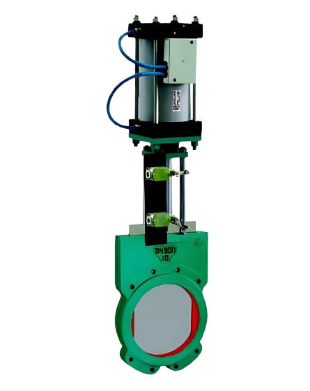
 PZ643TC Pneumatic Ceramic Wear-Resistant Knife Gate Valve
Model:
PZ643TC-6C/PZ643TC-10C/PZ643TC-16C/PZ643TC-6P/PZ643TC-10P//PZ643TC-16PSpecification:
DN50-DN600Pressure:
PN6-PN16Material:
Pulp slurry, etc. -
 ZZJ Pneumatic Slurry Valve
Model:
ZZJ-6C/ZZJ-10C/ZZJ-6P/ZZJ-10P/ZZJ-6R/ZZJ-10RSpecification:
DN50~600Pressure:
PN0.6~1.0MPaMaterial:
Cast Steel,Stainless Steel,Duplex Stainless Steel
What are the structural characteristics of knife gate valves? A detailed explanation of their six major advantages and application areas
Description: This article provides a detailed analysis of the unique structure, six core characteristics, and working principle of knife gate valves. It explains how they achieve automatic control through accessories and are widely used in industries such as chemical, paper, and wastewater treatment. They are ideal sealing and throttling valves.
Text:
The knife gate valve, as a high-performance industrial valve, is widely used in various fields such as chemical industry, coal, sugar manufacturing, sewage, paper making, etc., due to its unique structure and excellent performance. It is particularly suitable for regulating, throttling, and cutting off media in pipelines. This article will provide an in-depth analysis of the structural composition and core characteristics of the knife gate valve.
I. Basic Structure and Working Principle of Knife Gate Valve The knife gate valve is primarily composed of left/right valve bodies, U-shaped sealing rings, gate plates, valve stems, brackets, and driving devices (such as cylinders). Its core opening and closing actions are typically driven by cylinders. With supporting accessories such as solenoid valves and proximity switches, it can easily achieve on-off control, signal feedback, or continuous automatic adjustment, demonstrating a high degree of automation integration.
II. Six Core Structural Features of Knife Gate Valves The excellent performance of knife gate valves stems from their carefully designed structure, which is mainly reflected in the following six aspects:
The wafer-style design is compact and lightweight. Utilizing an advanced wafer-style connection structure, it significantly reduces the volume and weight compared to traditional flange valves, saving installation space and reducing the load on the pipeline system.
The full-bore flow passage provides a completely open straight-through channel when the non-clogging valve is opened, allowing the medium to pass through unimpeded. This design effectively prevents the deposition and clogging of media such as slurry and particles within the valve body, making it particularly suitable for applications involving fibers or solid particles, such as in paper making and wastewater treatment.
U-shaped seal ring, excellent sealing performance. A specially designed elastic U-shaped seal ring is used as the main seal, which can adaptively compensate for wear, ensuring that the valve maintains good bidirectional sealing performance and low leakage rate even after long-term use.
The elastic valve seat facilitates the maintenance of the gate plate's external seal, which is achieved by an elastic sealing strip embedded in the valve body. This sealing strip can be adjusted or quickly replaced using screws and a pressure plate, making maintenance simple and greatly extending the service life of the valve while reducing maintenance costs.
Streamlined design ensures minimal flow resistance. Due to the straight and smooth channels, as well as the thin and sharp gate plate (shaped like a blade), the flow resistance experienced by the medium is negligible, contributing to a reduction in system energy consumption.
Modular structure, convenient for installation and maintenance. The overall structure is designed to be simple and highly modular, making installation, disassembly, and routine maintenance very convenient, significantly reducing downtime for maintenance.
III. Summary of Application Scenarios Due to its prominent features of anti-clogging, easy adjustment, good sealing, and low flow resistance, the knife gate valve has become an ideal choice for handling harsh working conditions such as viscous media, slurry, dust mixtures, and sewage. It plays an irreplaceable key role in pulp adjustment in the paper industry, material liquid transportation in the chemical industry, emission control in sewage treatment plants, and solid material pipelines in industries such as coal and sugar manufacturing.
In summary, the knife gate valve is a valve solution that highly combines practicality, reliability, and economy. Its innovative structural design directly addresses common pain points in industrial applications, making it an indispensable and important component in modern process industry pipeline systems.
Rewriting instructions:
Enhance title and keyword layout: Optimize the title according to SEO requirements, extract core keywords such as "structural features", "advantages", and "application areas", and distribute them reasonably.
Optimize content structure and hierarchy: Adjust the segmentation of the original text, adopt hierarchical headings and bullet points, and enhance the coherence and readability of the information.
Supplementary induction and summary of applicable scenarios: Add a summary paragraph to highlight the comprehensive value of the product, enhancing the depth of content and user reference value.
If you prefer a more lively or technical document style, I can continue to optimize and adjust it for you.
Address:No. 1, Linxia Road, Sanqiao Industrial Zone, Oubei Sub-district, Yongjia County, Zhejiang Province| Switchboard:0577-67198981| mobile:+8613388552747| Email:sales@shanliuvalve.com|
COPYRIGHT © Zhejiang Shanliu Valve Technology Co., Ltd. Main Business: Water Valve Industrial valve|
浙ICP备2026020749号![]()