Your location:
 /
valves
/
More water supply and drainage valves
/
Hydraulic Control Valve
/
100X Diaphragm Remote Float Valve
/
valves
/
More water supply and drainage valves
/
Hydraulic Control Valve
/
100X Diaphragm Remote Float Valve

Mark Classification of Fluid products
- Phone:+86(577)67198981
- Fax:+86(577)67038872
- mobile:+8613388552747
- Sales Email 1:Karrie@shanliuvalve.com
- Sales Email 2:Yannie@shanliuvalve.com
- Sales Email 3:Merry@shanliuvalve.com
- Sales Email 4:Lucas@shanliuvalve.com
- Email:sales@shanliuvalve.com

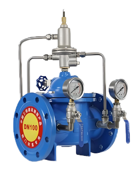
100X Diaphragm Remote Float Valve
- Model:100X-10/100X-16/100X-25/100X-10P/100X-16P/100X-25P
- Specification:DN50~DN400
- Temperature:≤80℃
- Medium:Water, a medium similar to water.
- Pressure:PN10~PN25
- Connection method:flange
- Driving method:Spring, automatic
- Material:Cast iron, stainless steel


Add QR code to serve you!
- Product Overview
- Performance Data
- Size Weight
Product Introduction
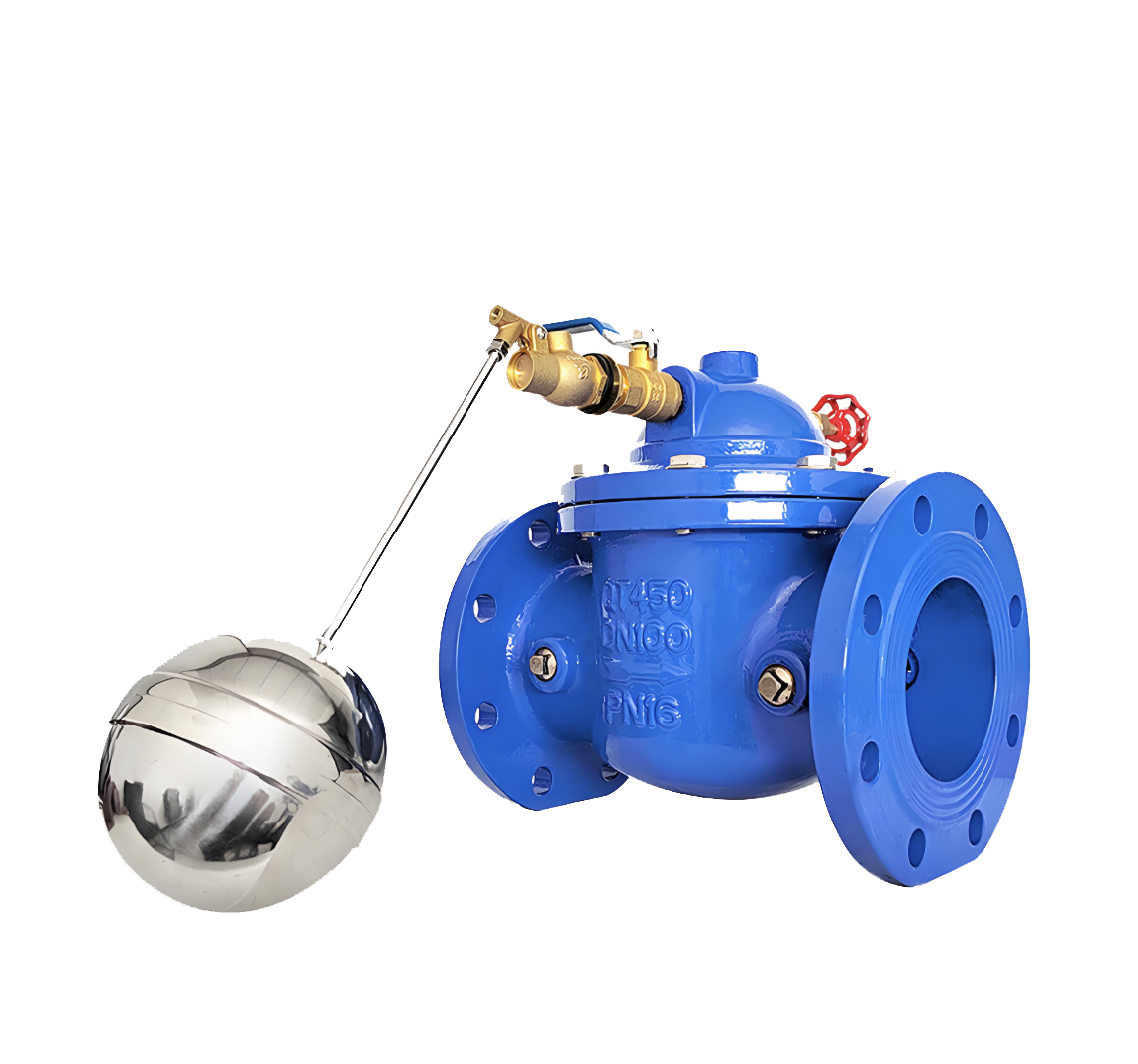
This product is designed and manufactured by our engineering and technical personnel with reference to advanced products of the same type at home and abroad. This valve is commonly used in automatic water supply systems for various types of water pools and towers such as high-rise buildings, industrial and mining enterprises, parks, etc. It has the characteristics of small size, light weight, easy installation and maintenance, and the main valve and float valve can be separated. The valve body adopts a full channel streamline design, with low fluid resistance, high flow rate, and good sealing effect. Due to the installation of a backflow control system on the main valve, which utilizes hydraulic automatic operation, the liquid level of the water tower or pool can be automatically controlled. It is easy to maintain, flexible and durable, with high accuracy in liquid level control. The water level is not affected by water pressure interference and is tightly closed without leakage. Welcome to purchase.

100X Diaphragm Remote Control Float Ball Valve Product Diagram
working principle
When water is supplied from the inlet end of the valve through the pipeline, since needle valve 14, ball valve 8, and float valve 5 are normally open, the water enters the valve cover control room through micro filter 13 and needle valve 14, and then flows into the water tank through ball valve 8 and float valve 5. If pressure cannot be formed in the control room, the inlet pressure under the main valve disc will lift the main valve disc and open it to supply a large amount of water to the water tank. When the water level in the pool or water tower gradually rises and the float ball is lifted and the float valve 5 is closed, the pressure of the water in the valve cover control room gradually increases until the main valve disc is closed, which then plays the role of automatic remote control. When the water level drops to a certain extent, the float ball valve is opened as the water level drops, controlling the flow of water in the control room. The pressure drops and lifts the main valve disc to replenish the water storage in the pool or tower in a timely manner. (This is the working principle of diaphragm type, and the same applies to piston type.)
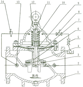
Structural diagram of 100X diaphragm remote control float valve
The valve consists of a main valve, needle valve, ball valve, float valve, and micro filter, as shown in the figure.
The structural form is a hydraulic control cut-off form, which adopts rubber diaphragm and piston connected valve disc opening and closing forms according to different diameters.
Main Components and Materials
| 编号Number | 零件名称Part Name | 材 质Material |
| 1 | 阀 体Valve Body | 铸铁、不锈钢Cast Iron.Stainless Steel |
| 2 | 阀 座Valve Seat | 铜、不锈钢Copper.Stainless Steel |
| 3 | 密封垫Gasket | 强化橡胶Reinforced Rubber |
| 4 | 密封垫压板Gasket Pressure Plate | 铜、不锈钢Copper.Stainless Steel |
| 5 | 浮球阀Float Valve | 青 铜Bronze |
| 6 | 阀 盘Valve Disc | 铜、不锈钢Copper.Stainless Steel |
| 7 | 膜 片Diaphragm | 强化橡胶Reinforced Rubber |
| 8 | 球 阀Ball Valve | 铜Copper |
| 9 | 膜片压板Diaphragm Pressure Plate | 铜、不锈钢Copper.Stainless Steel |
| 10 | 弹 簧Spring | 不锈钢Stainless Steel |
| 11 | 阀 杆Valve Stem | 不锈钢Stainless Steel |
| 12 | 阀 盖Valve Cover | 铸铁、不锈钢Cast Iron.Stainless Steel |
| 13 | 微型过滤器Micro Filter | 不锈钢Stainless Steel |
| 14 | 针阀Needle Valve | 铜Copper |
Main Technical Performance
| Nominal Pressure | 1.0 MPa | 1.6MPa | 2.5MPa |
| Shell Test Pressure | 1.5MPa | 2.4MPa | 3.75MPa |
| Seal Test Pressure | 1.1MPa | 1.76MPa | 2.75MPa |
| Applicable Temperature | 0℃~80℃ | ||
| Applicable Medium | Water | ||
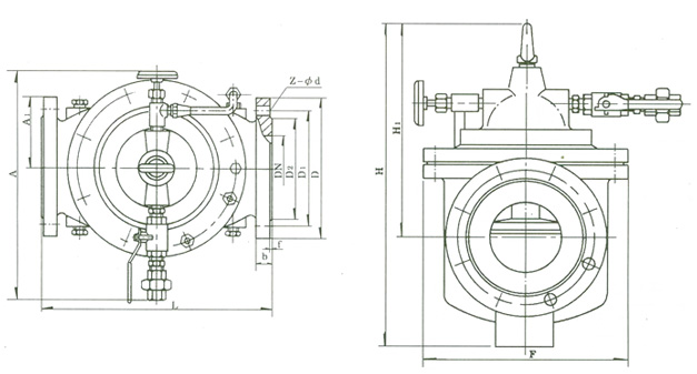
100X Diaphragm Remote Control Float Ball Valve Outline Dimensional Drawing
Installation Dimension Table
| Nominal Diameter | Dimension(mm) | |||||||||||||||||
| L | D | D1 | D2 | Z-фd | A1 | A | H1 | H | F | |||||||||
| PN10 | PN16 | PN25 | PN10 | PN16 | PN25 | PN10 | PN16 | PN25 | PN10 | PN16 | PN25 | |||||||
| 50 | 240 | 165 | 165 | 165 | 125 | 125 | 125 | 102 | 102 | 99 | 4-ф18 | 4-ф18 | 4-ф18 | 140 | 335 | 210 | 265 | 170 |
| 65 | 250 | 185 | 185 | 185 | 145 | 145 | 145 | 122 | 122 | 118 | 4-ф18 | 4-ф18 | 8-ф18 | 140 | 335 | 215 | 310 | 180 |
| 80 | 255 | 200 | 200 | 200 | 160 | 160 | 160 | 133 | 133 | 132 | 8-ф18 | 8-ф18 | 8-ф18 | 145 | 345 | 245 | 350 | 210 |
| 100 | 360 | 220 | 220 | 235 | 180 | 180 | 190 | 158 | 158 | 156 | 8-ф18 | 8-ф18 | 8-ф22 | 155 | 365 | 305 | 460 | 275 |
| 125 | 400 | 250 | 250 | 270 | 210 | 210 | 220 | 184 | 184 | 184 | 8-ф18 | 8-ф18 | 8-ф26 | 165 | 385 | 365 | 520 | 310 |
| 150 | 455 | 285 | 285 | 300 | 240 | 240 | 250 | 212 | 212 | 211 | 8-ф22 | 8-ф22 | 8-ф26 | 180 | 410 | 415 | 570 | 355 |
| 200 | 585 | 340 | 340 | 360 | 295 | 295 | 310 | 268 | 268 | 274 | 8-ф22 | 12-ф22 | 12-ф26 | 205 | 465 | 510 | 840 | 460 |
| 250 | 650 | 395 | 405 | 425 | 350 | 355 | 370 | 320 | 320 | 330 | 12-ф22 | 12-ф26 | 12-ф30 | 225 | 505 | 560 | 890 | 500 |
| 300 | 800 | 445 | 460 | 485 | 400 | 410 | 430 | 370 | 370 | 389 | 12-ф22 | 12-ф26 | 16-ф30 | 245 | 545 | 658 | 1030 | 580 |
| 350 | 860 | 505 | 520 | 555 | 460 | 470 | 490 | 430 | 430 | 448 | 16-ф22 | 16-ф26 | 16-ф33 | 275 | 595 | 696 | 1090 | 640 |
| 400 | 960 | 565 | 580 | 620 | 515 | 525 | 550 | 482 | 482 | 503 | 16-ф30 | 16-ф30 | 16-ф36 | 285 | 625 | 735 | 1150 | 715 |
-
 600X Piston-type Hydraulic Electric Control Valve
Model:
600X-10/600X-16/600X-25/600X-10P/600X-16P/600X-25PSpecification:
DN350~DN800Pressure:
PN10~PN25Material:
Cast Iron, Stainless Steel -
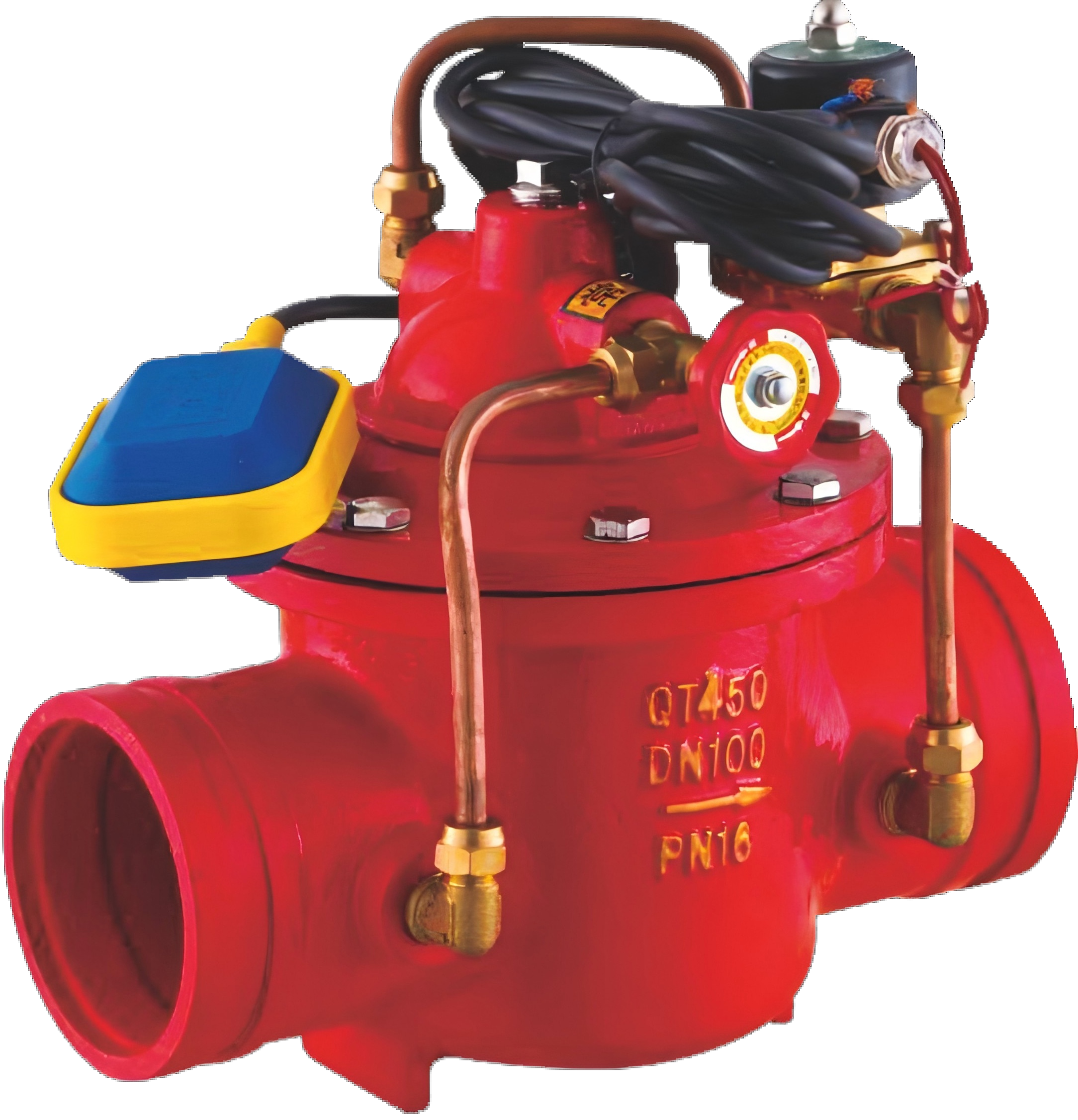 G106X groove hydraulic electric floating ball control valve
Model:
G106X-10/G106X-16/G106X-10Q/G106X-16Q/G106X-10P/G106X-16P/G106X-10T/G106X-16TSpecification:
DN50-DN600Pressure:
PN10~PN16Material:
Cast iron, ductile iron, stainless steel, copper -
 800X Differential Pressure (Bypass) Valve
Model:
800X-10P/800X-16P/800X-10T/800X-16TSpecification:
DN50~DN600Pressure:
PN10~PN16Material:
stainless steel, copper
Address:No. 1, Linxia Road, Sanqiao Industrial Zone, Oubei Sub-district, Yongjia County, Zhejiang Province| Switchboard:0577-67198981| mobile:+8613388552747| Email:sales@shanliuvalve.com|
COPYRIGHT © Zhejiang Shanliu Valve Technology Co., Ltd. Main Business: Water Valve Industrial valve|
浙ICP备2026020749号![]()