Your location:
 /
valves
/
More water supply and drainage valves
/
Hydraulic Control Valve
/
valves
/
More water supply and drainage valves
/
Hydraulic Control Valve

Mark Classification of Fluid products
-
Hydraulic Control Valve
-
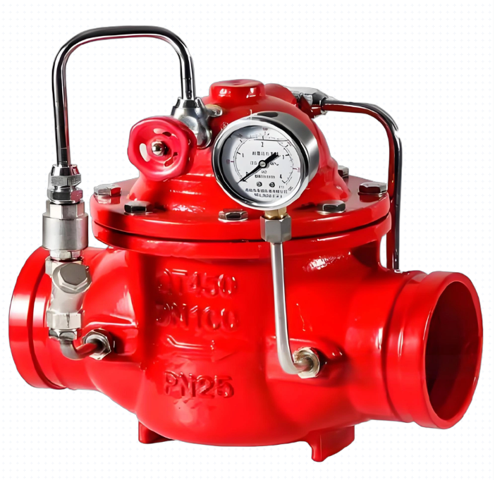
JD745X Multifunctional Water Pump Control Valve
-
100X Diaphragm Remote Float Valve
-
200X Diaphragm Pressure Reducing Valve
-
300X Diaphragm type Slow closing Check Valve
-

400X Diaphragm Type Flow Control Valve
-
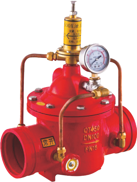
500X Diaphragm Pressure Relief/Holding Valve
-
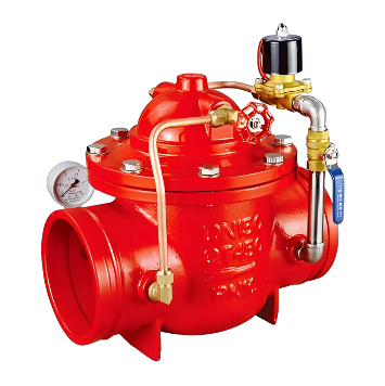
600X Diaphragm Hydraulic Electric Control Valve
-
700X Diaphragm Pump Control Valve
-
800X Differential Pressure (Bypass) Valve
-

900X Diaphragm Emergency Shut-off Valve
-

100X Remote Control Float Valve
-

200X Piston Type Pressure Reducing Valve
-

300X Piston Type Slow-closing Check Valve
-
400X Piston Type Flow Control Valve
-

500X Piston Type Pressure Relief/Sustaining Valve
-

600X Piston-type Hydraulic Electric Control Valve
-

700X Piston Pump Control Valve
-
900X Piston Emergency Shut-off Valve
-
H142X Hydraulic Water Level Control Valve
-
J145X Electric Remote Control Valve
-
AX742X Safety Relief/Pressure Retaining Valve
-
Model F745X Remote Control Float Valve
-
F8745X groove fire pump control valve
-
G100X remote control floating ball valve for groove
-
G106X groove hydraulic electric floating ball control valve
-
G200X fire pressure reducing valve
-
G300X groove slow closing check valve
-
G500X groove pressure relief valve
-
G600X groove hydraulic electric control valve
-
MoreMore water supply and drainage valves>>
-
More valve products>>
- Phone:+86(577)67198981
- Fax:+86(577)67038872
- mobile:+8613388552747
- Sales Email 1:Karrie@shanliuvalve.com
- Sales Email 2:Yannie@shanliuvalve.com
- Sales Email 3:Merry@shanliuvalve.com
- Sales Email 4:Lucas@shanliuvalve.com
- Email:sales@shanliuvalve.com

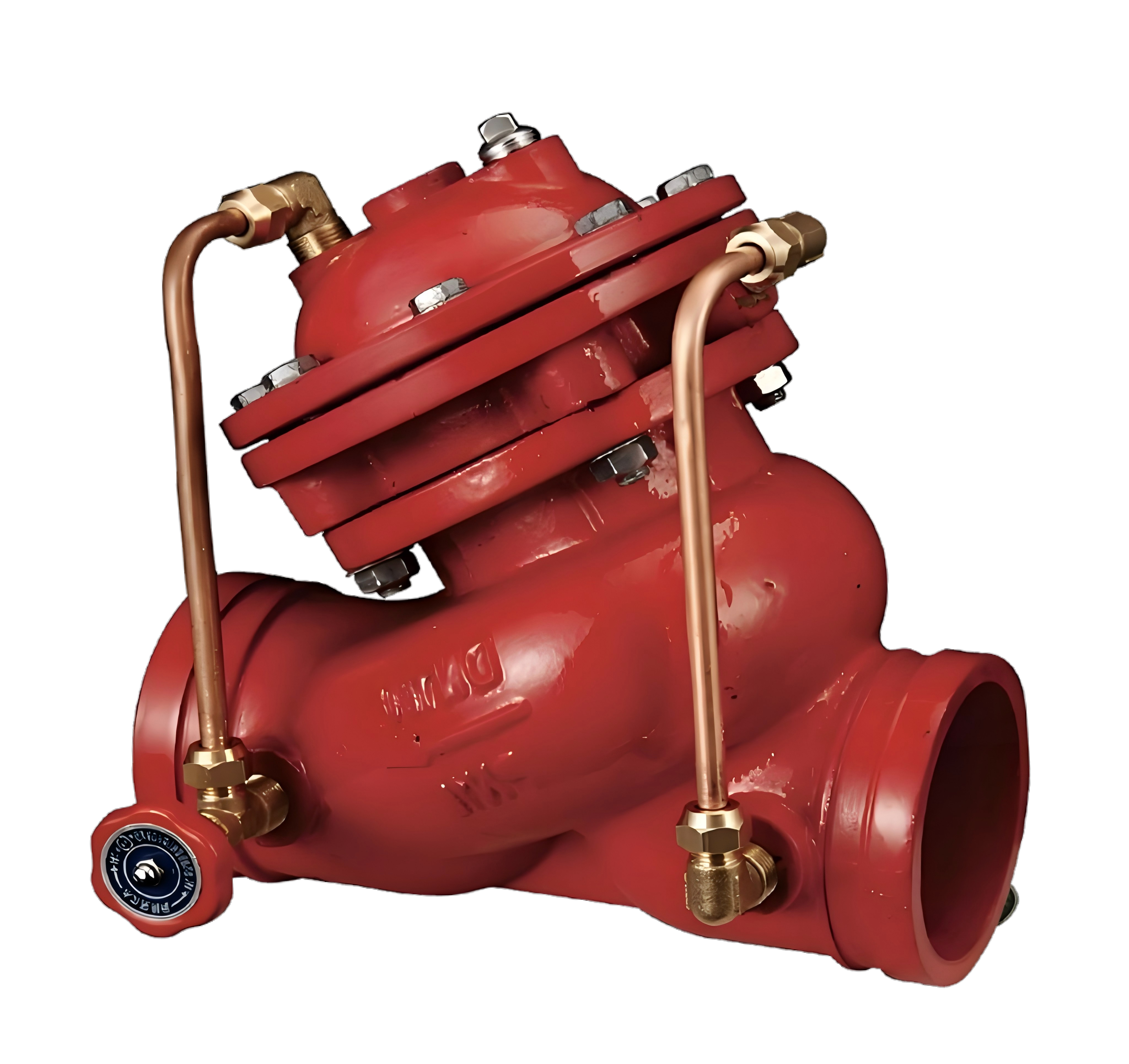
Hydraulic Control Valve
Hydraulic control valve is a multi-purpose valve with diverse valve functions depending on the different configurations of accessories. It is composed of a main valve and its external needle valve, pilot valve, solenoid valve, float valve, and pipeline combination. Hydraulic control valve is a general term for a series of multi-purpose control and safety valves. Mainly including: remote control float valve, liquid level control valve, holding pressure reducing valve, slow closing check valve, flow control valve, differential pressure control valve, pressure relief holding valve, electric remote control valve, multifunctional water pump control valve, emergency shut-off valve, diaphragm hydraulic control valve, piston hydraulic control valve, etc. The main characteristics of the hydraulic control valve produced by Zhejiang Shanliu Valve Technology are: it utilizes the pressure of the medium itself and the operation of the hydraulic system in its mode of action, and can be automatically controlled, with accurate action and reliable performance. It can be widely used in daily life, production, fire protection, water supply and drainage system pipelines to play a control and safety role.
-
JD745X Multifunctional Water Pump Control Valve
Model:
JD745X-10/JD745X-16/JD745X-25/JD745X-10Q/JD745X-16Q/JD745X-25Q/JD745X-10P/JD745X-16P/JD745X-25PSpecification:
DN50~DN1000Pressure:
PN10~PN25Material:
Cast Iron, Cast Steel, Stainless SteelPurposeThe multifunctional water pump control valve is mainly installed on the outlet pipeline of water pumps in high-rise building water supply systems and other water supply systems. It prevents medium backflow, water hammer, and water hammering phenomena. The valve integrates the functions of an electric valve, check valve, and water hammer arrester, effectively improving the safety and reliability of the water supply system. It meets the requirements of mechanization and automation for water supply engineering equipment.Product Diagram of JD745X Multifunctional Water Pump Control ValveFeatures1.Excellent water hammer elimination: Integrates the technical principles of slow opening, fast closing, and slow closing to eliminate water hammers, preventing water hammers during pump start and stop.2.Convenient operation: Only requires operating the pump motor on/off button, and the valve automatically opens and closes according to pump operation procedures.3.Good energy-saving effect: The valve body adopts a streamlined DC design, with low pressure loss, large flow, and small volume and light weight.4.Dual-chamber transmission mechanism: Divided into two different pressure chambers, featuring stable water-stop closing without pressure fluctuations. Additionally, the entire transmission mechanism can be disassembled as a whole without removing the diaphragm, facilitating inspection.Working PrincipleThe multifunctional water pump control valve consists of a main valve and a conduit control system. The main valve includes the valve body, valve cover, valve stem, large and small valve discs, diaphragm, and diaphragm pressure plate. The upper and middle valve covers, valve stem, diaphragm, diaphragm pressure plate, and small valve disc form an integrated dual-chamber transmission mechanism, divided by the diaphragm. The large valve disc slides up and down on the valve stem. The conduit control system includes ball valves, micro check valves, filters, and pipelines, connecting the main valve inlet to the lower chamber of the control room and the outlet to the upper chamber.When the pump starts: The inlet pressure rises, and water flows through the ball valve (14), filter (13), and micro check valve (12) into the lower chamber, pushing the diaphragm pressure plate up to open the small valve disc. The large valve disc opens simultaneously with the small one under water flow, completing valve opening. Water in the upper chamber flows to the outlet through filter (10) and ball valve (6). The throttling effect of the micro check valve (12) slows the opening speed, ensuring the valve opens longer than the pump motor starts to avoid water hammers.When the pump stops: The inlet pressure is lower than the outlet pressure. The large valve disc falls rapidly to close, cutting off about 90% of the flow. Outlet pressure water enters the upper chamber, pushing the diaphragm pressure plate down to close the small valve disc. Adjusting the ball valve (6) at the outlet controls the closing speed of the small valve disc to eliminate water hammers.View detail>>
-
100X Diaphragm Remote Float Valve
Model:
100X-10/100X-16/100X-25/100X-10P/100X-16P/100X-25PSpecification:
DN50~DN400Pressure:
PN10~PN25Material:
Cast iron, stainless steelProduct IntroductionThis product is designed and manufactured by our engineering and technical personnel with reference to advanced products of the same type at home and abroad. This valve is commonly used in automatic water supply systems for various types of water pools and towers such as high-rise buildings, industrial and mining enterprises, parks, etc. It has the characteristics of small size, light weight, easy installation and maintenance, and the main valve and float valve can be separated. The valve body adopts a full channel streamline design, with low fluid resistance, high flow rate, and good sealing effect. Due to the installation of a backflow control system on the main valve, which utilizes hydraulic automatic operation, the liquid level of the water tower or pool can be automatically controlled. It is easy to maintain, flexible and durable, with high accuracy in liquid level control. The water level is not affected by water pressure interference and is tightly closed without leakage. Welcome to purchase.100X Diaphragm Remote Control Float Ball Valve Product Diagramworking principleWhen water is supplied from the inlet end of the valve through the pipeline, since needle valve 14, ball valve 8, and float valve 5 are normally open, the water enters the valve cover control room through micro filter 13 and needle valve 14, and then flows into the water tank through ball valve 8 and float valve 5. If pressure cannot be formed in the control room, the inlet pressure under the main valve disc will lift the main valve disc and open it to supply a large amount of water to the water tank. When the water level in the pool or water tower gradually rises and the float ball is lifted and the float valve 5 is closed, the pressure of the water in the valve cover control room gradually increases until the main valve disc is closed, which then plays the role of automatic remote control. When the water level drops to a certain extent, the float ball valve is opened as the water level drops, controlling the flow of water in the control room. The pressure drops and lifts the main valve disc to replenish the water storage in the pool or tower in a timely manner. (This is the working principle of diaphragm type, and the same applies to piston type.)View detail>>
-
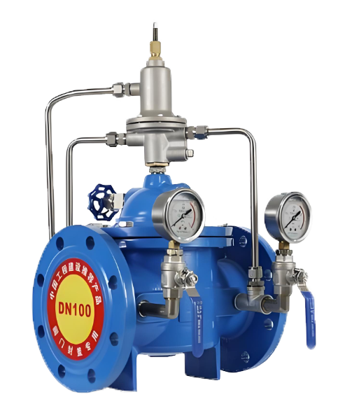
200X Diaphragm Pressure Reducing Valve
Model:
200X-10/200X-16/200X-25/200X-10Q/200X-16Q/200X-25Q/200X-10P/200X-16P/200X-25P/200X-10T/200X-16T/200X-25TSpecification:
DN50~DN400Pressure:
PN10~PN25Material:
Cast iron, ductile iron, stainless steel, copperProduct IntroductionThe 200X diaphragm pressure reducing valve is designed and manufactured by our unit's nominal technical personnel with reference to advanced products of the same type in the United States, France, and China. Suitable for use in industrial and mining enterprises, high-rise buildings, domestic water, and fire water systems, it can replace intermediate water tanks in situations where static and dynamic pressure reduction is required, saving the cost of intermediate water tanks in buildings and expanding the space for building use. The valve body adopts a full channel streamline design, with low fluid resistance and high flow rate. Hydraulic operation is adopted in the transmission mode, which uses the water pressure in the pipeline to automatically operate the up and down movement of the main valve disc, control the valve opening, adjust the downstream pressure, and maintain the downstream pressure at the pressure value set by the pilot valve spring. When the downstream pressure exceeds the set value, the pressure reducing valve will automatically close, and regardless of the fluctuation of the inlet pressure P1, a stable outlet pressure P2 can be output. No matter how the downstream flow changes, the outlet pressure P2 can be maintained stable at the set value of the pilot valve. At the same time, the outlet pressure adjustment range regulated by the pilot valve is large, reaching 10-80% of the pre valve pressure, and it works smoothly without water hammer impact.Product diagram of 200X diaphragm pressure reducing valveworking principle of 200X Diaphragm Pressure Reducing ValveThe inlet pressure P1 enters the control chamber of the main valve through the conduit and needle valve 18 (see structural diagram), and establishes a downward pressure P3. The outlet pressure P2 also acts on the diaphragm (or piston) of the pilot valve through the conduit and opposes the regulating spring of the pilot valve. When the downstream pressure exceeds the set value of the pilot valve spring, the pilot valve closes, and the water discharge in the control chamber is 0. When the variable pressure P3 reaches its maximum value, the main valve disc tightly presses the valve seat and the pressure reducing valve closes. Once the downstream pressure P2 drops to the set value of the pilot valve spring, the pilot valve opens and the pressure water in the control room will be discharged downstream through pilot valve 9 and ball valve 6. Due to the small opening of the needle valve and the smaller diameter of the inlet duct compared to the outlet duct, the discharge rate is greater than the inlet pressure replenishment rate. As a result, the pressure P2 in the control room decreases, and the inlet pressure P1, which has been acting under the main valve disc, lifts the main valve disc and opens the pressure reducing valve. In the fixed adjustment state, the discharge flow rate is equal to the replenishment flow rate, the opening of the main valve remains unchanged, and the downstream pressure is stable. (This is the working principle of diaphragm type, and the same applies to piston type.)View detail>>
-
300X Diaphragm type Slow closing Check Valve
Model:
300X-10/300X-16/300X-25/300X-10P/300X-16P/300X-25PSpecification:
DN50~DN400Pressure:
PN10~PN25Material:
Cast iron, stainless steelProduct IntroductionThe 300X diaphragm type slow closing check valve is a new type of check valve developed by our technical personnel based on advanced products of the same type at home and abroad. This valve has the characteristics of novel structure, reasonable design, good sealing effect, low fluid resistance, high flow rate, and long service life. Due to the installation of a conduit control system on the main valve and the use of hydraulic automatic operation, the main valve can achieve the best opening or closing speed, thereby preventing the occurrence of water hammer and water hammer, and achieving the effect of slow closing and noise reduction. It is an ideal product for high-rise building water supply systems. Welcome to purchase!Product diagram of 300X diaphragm type slow closing check valveworking principleWhen the water pump starts working, the water flow at the inlet end of the valve passes through the micro filter 16, needle valve 15, one-way valve 14, enters the control room of the valve cover, and then is discharged to the outlet through the ball valve 6. Due to the small opening of needle valve 15 (usually 1/4 turn) and the smaller diameter of the inlet duct compared to the outlet duct, the discharge rate in the control room is greater than the water replenishment rate at the inlet. As a result, the pressure in the control room decreases, and the inlet pressure that has been acting under the main valve disc 5 lifts the main valve disc, thereby opening the main valve to supply water downstream. When the water supply is stopped, the downstream water begins to flow back. Due to the weight of the valve disc 5 and the pressure in the upper water chamber, 90% of the shut-off port is quickly closed, and the remaining 10% is transmitted to the upper water chamber through a conduit. Due to the action of the one-way valve 14, the water in the upper water chamber cannot flow out, so the pressure in the water chamber gradually increases, and the valve stem slowly moves down. Finally, the main valve disc is tightly closed, preventing downstream water from flowing back and playing a role in slow closing and noise reduction. (This is the working principle of diaphragm type, and the same applies to piston type.)View detail>>
-
400X Diaphragm Type Flow Control Valve
Model:
400X-10/400X-16/400X-25/400X-10P/400X-16P/400X-25PSpecification:
DN50~DN400Pressure:
PN10~PN25Material:
Cast iron, stainless steel,Product IntroductionThis product has reached the advanced level of international similar products through the introduction of new technologies, manufacturing processes, and structural improvements by our engineering and technical personnel. The valve body adopts a full channel streamline design, with low fluid resistance and high flow rate. Hydraulic operation is adopted in the transmission mode, which uses the water pressure in the pipeline to automatically operate the up and down movement of the main valve disc and control the opening of the main valve port. The main valve is installed in the pipeline of the water supply and distribution pipeline to control the flow rate. You can first set a fixed flow rate for the upper guide regulating valve and the guide valve to keep the flow through the main valve constant, even if the pressure upstream of the main valve changes, it will not affect it. In short, this product is an ideal choice for domestic water supply, fire protection systems, and industrial water supply systems.400X Diaphragm Type Flow Control Valve product imageworking principleWhen the water pressure at the inlet end of the main valve enters the valve body and control chamber respectively (see structural diagram), and the ball valve 6 outside the main valve is closed at the same time, the main valve is in a fully closed state. When the ball valve 6 outside the main valve is fully opened, and the water pressure in the control room is fully arranged in the downstream low-pressure area, the main valve is in a fully open state. Adjust the opening of ball valve 6 outside the main valve to achieve balance between the water flow passing through needle valve 17 and ball valve 6. At this point, the main valve is in a floating state.The flow control valve utilizes the pressure difference between the water flow entering the main valve control chamber through the conduit and needle valve 17, and is led to and controlled by the spring of the regulating conduit 9 to adjust the valve opening. The upper part of the main valve is adjusted to guide the regulating valve 15 to ensure the set opening of the main valve port, so that the flow in the pipeline does not exceed a certain set value. Even if the upstream pressure changes, it will not affect the downstream pressure. (This is the working principle of diaphragm type, and the same applies to piston type.)View detail>>
-
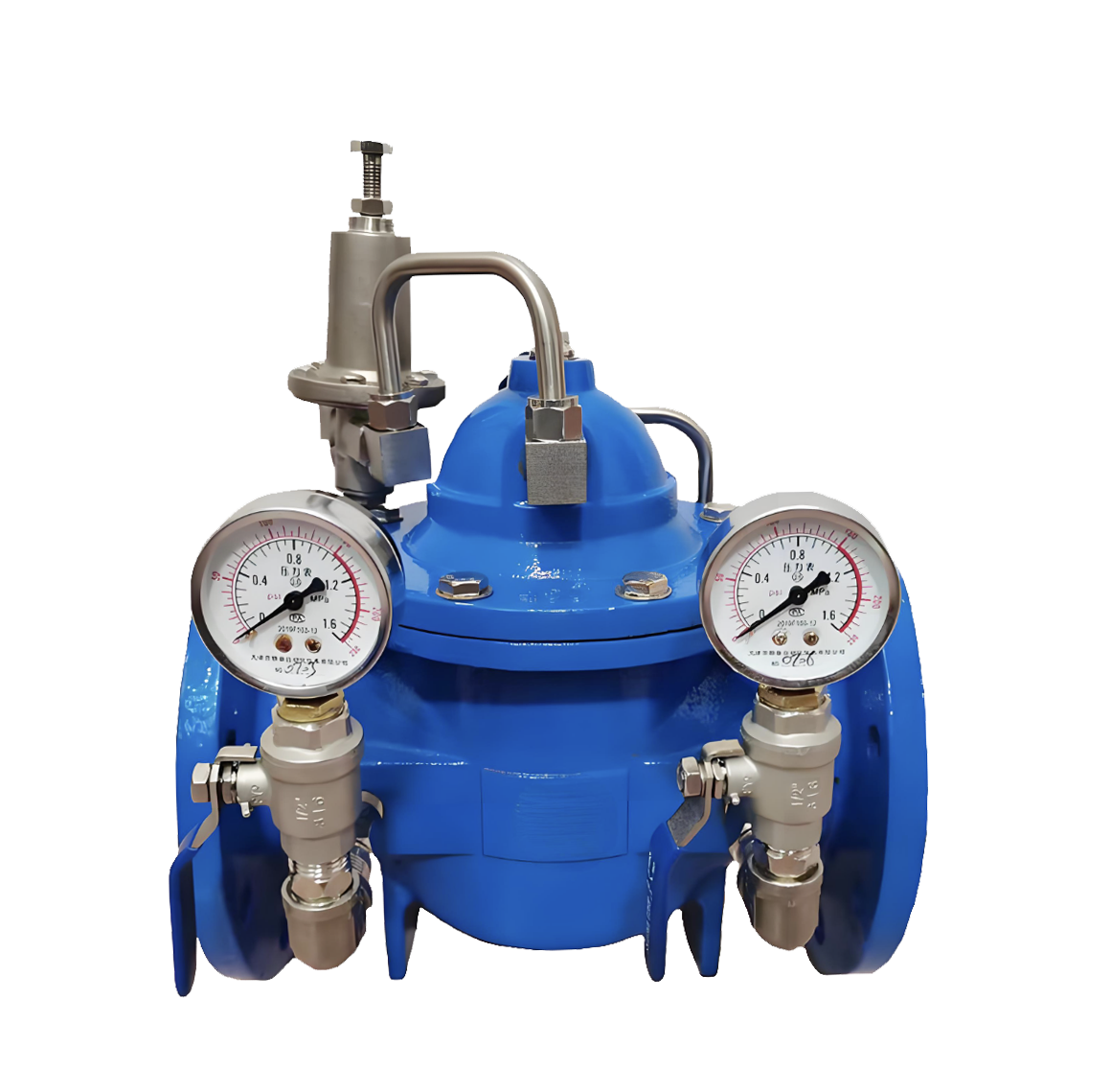
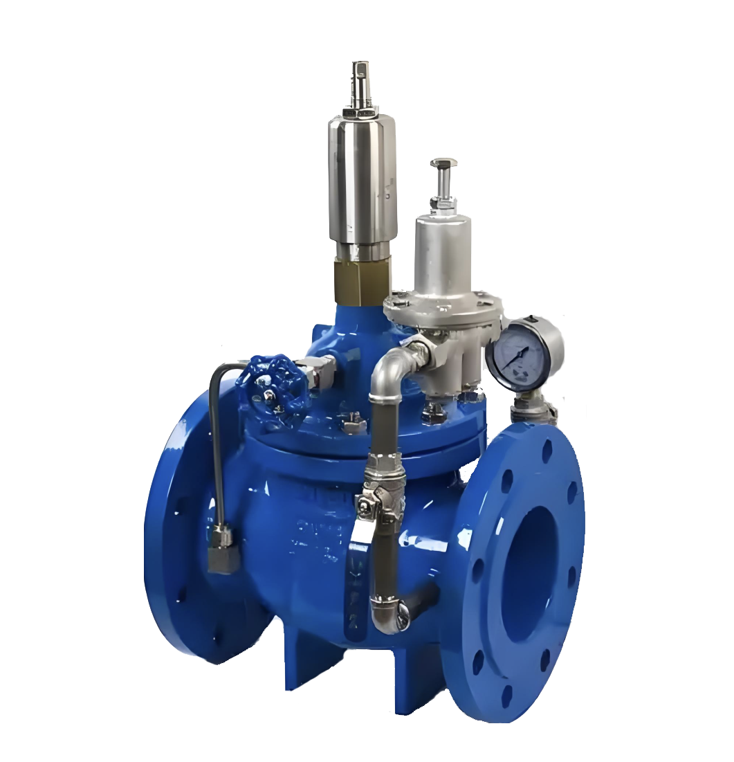
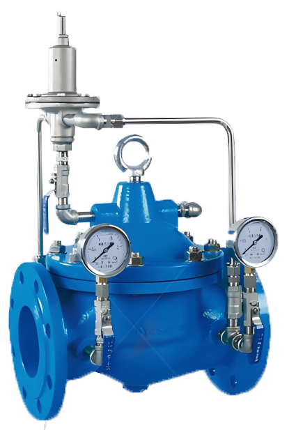
500X Diaphragm Pressure Relief/Holding Valve
Model:
500X-10/500X-16/500X-25/500X-10P/500X-16P/500X-25PSpecification:
DN50~DN400Pressure:
PN10~PN25Material:
Cast Iron, Stainless SteelProduct IntroductionThe 500X diaphragm pressure relief/holding valve is a new type of valve developed by our engineering and technical personnel with reference to advanced products of the same type in the United States, France, and China. Hydraulic operation is adopted in the transmission mode and can be automatically controlled, that is, the pressure difference in the control pipeline is used to automatically open and close the main valve, so that the upstream pressure does not exceed a certain set value. The valve body adopts a full channel streamline design, with low fluid resistance, good sealing performance, and sensitive automatic opening and closing performance. The main feature of this valve is that it can be used as both a pressure relief valve and a pressure holding valve. When making a pressure relief valve, it can release the pressure in the water supply pipeline that exceeds the safety setting value of the guide valve, and maintain the pressure in the pipeline below the safety setting value to prevent high pressure or sudden pressure damage to the pipeline or equipment. It can be used for pressure relief in high-rise building fire testing circulation systems and other horizontal systems to prevent system danger caused by high water pressure; When operating a pressure holding valve, the upstream water supply pressure of the main valve can be maintained above a certain set value to ensure the pressure in the upstream water supply area of the main valve. Mainly used in urban low-pressure water supply areas. In short, this product is an ideal choice for water supply systems. Welcome to purchase.500X diaphragm type pressure relief and holding valve product imageWorking principle and purposeWhen making a pressure relief valve, the main valve is installed in parallel with the main pipeline in the drainage bypass. When the upstream pressure gradually rises above the set value of pilot valve 13, the main valve quickly opens to release water and reduce pressure until the upstream pressure drops below the set value of pilot valve 13. Only then does the main valve slowly and smoothly close, avoiding water hammer and ensuring the safety of the pipeline. When making a pressure relief valve, it is mainly used to eliminate the gradually increasing high pressure caused by flow supply exceeding demand, such as in the early stage of fire hydrant systems, automatic sprinkler systems, and at the outlet of various water supply systems. When making a pressure relief valve, ball valve 12 is normally open. When making a pressure holding valve, the main valve is installed on the main pipeline, that is, it is installed in series with the main pipeline. As long as the water supply pressure upstream of the main valve is lower than the set value of pilot valve 13, the main valve will be in a closed state. When the water supply pressure upstream of the main valve exceeds the set value of pilot valve 13, the main valve will automatically open and supply water downstream of the main valve, thereby ensuring the water supply pressure upstream of the main valve. Mainly used to maintain the minimum water supply pressure of urban main pipes, especially in case of fire, to prevent excessive pumping and pressure reduction by branch pipe users. When used as a pressure holding valve, ball valve 12 is normally closed or replaced with a plug.View detail>>
-
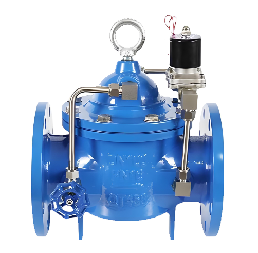
600X Diaphragm Hydraulic Electric Control Valve
Model:
600X-10/600X-16/600X-25/600X-10P/600X-16P/600X-25PSpecification:
DN50~DN400Pressure:
PN10~PN25Material:
Cast Iron, Stainless SteelProduct IntroductionThis product is designed and manufactured by the engineering and technical personnel of our unit with reference to advanced similar products at home and abroad. The valve body adopts a streamlined design, featuring small fluid resistance, large flow rate and excellent sealing performance. Equipped with a pipe control system with a solenoid valve as the pilot valve on the main valve, it uses hydraulic operation and is often used for automatic control in water supply, drainage and industrial systems. It is a valve that can be remotely controlled to open and close, and a speed control device can be added if needed. It can replace large electric devices for opening and closing gate valves and butterfly valves, with the advantages of small size, light weight, simple maintenance, convenient use, safety and reliability. Welcome to purchase!Product Drawing of 600X Diaphragm Hydraulic Electric Control ValveWorking PrincipleWhen the water pump starts operating, the water flow at the inlet end of the valve passes through the micro filter, needle valve 14, pressure control chamber, electromagnetic pilot valve 8, ball valve 6 in sequence, and is discharged to the outlet. At this time, the electromagnetic pilot valve is energized (the solenoid valve works synchronously with the water pump motor) and remains in a normally open state. Due to the small opening of needle valve 14 and the smaller diameter of the inlet pipe compared to the outlet pipe, the discharge speed in the control chamber is greater than the water replenishment speed. As a result, the pressure in the control chamber decreases, and the inlet pressure acting under the main valve disc lifts the main valve disc, thereby opening the main valve to supply water downstream.When water supply needs to be stopped, the water pump motor shuts down, and the electromagnetic pilot valve 14 closes due to power failure (normally closed state). Since the downstream water starts to flow back and the self-weight of the valve disc causes the throttle port to close quickly by 90%, the remaining 10% uses the pipe to transmit the pressure behind the valve to the upper water chamber. Due to the action of the electromagnetic pilot valve, the pressure in the upper water chamber gradually increases, eventually causing the main valve disc to close tightly. This prevents downstream water from flowing back, protects the water pump motor, and also plays a role in slow closing and noise elimination. (This is the working principle of the diaphragm type, and the piston type works similarly.)View detail>>
-
700X Diaphragm Pump Control Valve
Model:
700X-10/700X-16/700X-25/700X-10P/700X-16P/700X-25PSpecification:
DN50~DN400Pressure:
PN10~PN25Material:
Cast Iron Ductile Iron Carbon Steel Stainless SteelProduct Introductionct is designed and manufactured by our factory's engineers with reference to advanced domestic and foreign similar products. The valve body features a streamlined design, ensuring low fluid resistance, large flow rate, and excellent sealing performance. Equipped with a solenoid valve-guided pipeline control system, it operates hydraulically and is commonly used for automatic control in water supply, drainage, and industrial systems, enabling remote operation of valve opening and closing. It can be additionally fitted with a speed control device. This product replaces large electric devices for gate valves and butterfly valves, offering advantages such as small size, light weight, easy maintenance, convenient operation, safety, and reliability. Welcome to purchase!Product diagram of 700X Diaphragm Pump Control ValveWorking Principle the water pump starts operating, the water flow at the inlet end enters the valve cover control chamber through needle valve 3 and check valve 1, and then is discharged to the outlet through check valve 2, solenoid pilot valve 7, and ball valve 8. When the valve disc opens to 10%, it touches the electrical control switch, at which point the solenoid pilot valve is energized and remains in a normally closed state. Due to the small opening of needle valve 3 (usually 1/4 turn open) and the smaller diameter of the inlet pipe compared to the outlet pipe, the discharge speed in the control chamber is higher than the water replenishment speed. As a result, the pressure in the control chamber decreases, and the inlet pressure lifts the main valve disc to supply a large amount of water downstream. When water supply needs to be stopped, before the water pump shuts down, the inlet pressure first closes 90% of the main valve. At this time, the solenoid pilot valve 7 is in a normally open state due to power failure. For the remaining 10%, the pressure in the upper water chamber gradually increases through the action of solenoid pilot valve 7 and check valves 1 and 2, eventually closing the main valve disc tightly. This can completely prevent water hammer, protect the water pump motor, and also achieve slow closing and noise reduction.View detail>>
-
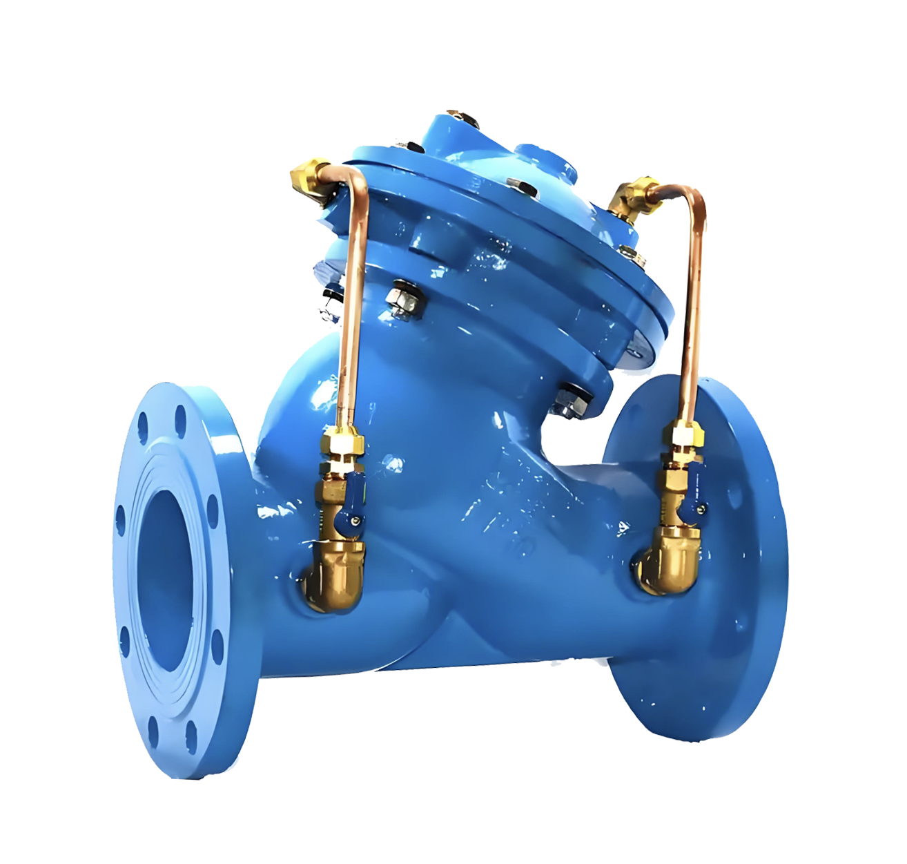
800X Differential Pressure (Bypass) Valve
Model:
800X-10P/800X-16P/800X-10T/800X-16TSpecification:
DN50~DN600Pressure:
PN10~PN16Material:
stainless steel, copperProduct IntroductionThe differential pressure (bypass) valve produced by our company is mainly applied between the water supply and return pipes of air conditioning systems. It maintains a fixed differential pressure between supply and return water, improves system energy efficiency, reduces noise, and prevents damage to system equipment caused by excessive differential pressure. The valve is mainly composed of a main valve and a differential pressure pilot valve.800X Differential Pressure (Bypass) ValveView detail>>
-
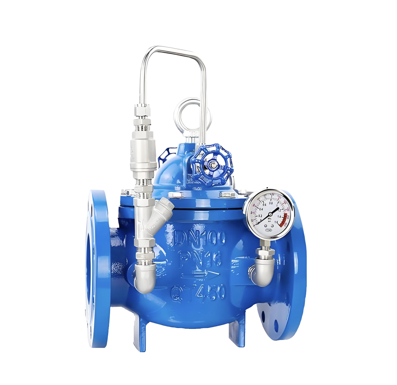
900X Diaphragm Emergency Shut-off Valve
Model:
900X-10/900X-16/900X-25/900X-10P/900X-16P/900X-25PSpecification:
DN50~DN400Pressure:
PN10~PN25Material:
Cast Iron, Stainless SteelProduct IntroductionThis product is designed and manufactured by our factory's engineering and technical personnel with reference to advanced products of the same type from the United States, France and other countries. It is suitable for parallel water supply systems in industrial enterprises, domestic water supply and fire water supply. During fire water supply, the valve automatically closes urgently to cut off domestic water supply and ensure fire water demand. After the fire is extinguished, the valve automatically opens to resume domestic water supply. It can replace the intermediate water tank in occasions requiring static pressure and dynamic pressure reduction, saving the cost of building intermediate water tanks and expanding the usable space of buildings. The valve body adopts a full-channel streamlined design, featuring low fluid resistance and large flow rate. Hydraulic operation is adopted for the transmission method—utilizing the water pressure in the pipeline to automatically drive the main valve disc up and down, control the valve port opening, adjust the downstream pressure, and maintain the downstream pressure at the set value of the pilot valve spring. When the downstream pressure exceeds the set value, the pressure reducing valve will automatically close. Regardless of fluctuations in the inlet pressure P1, a stable outlet pressure P2 can be output. It can adapt to downstream flow changes ranging from 10% to 80% of the inlet pressure, operating stably without water hammer impact.Product diagram of 900X Diaphragm Emergency Shut-off ValveWorking PrincipleWhen fire water is used, open Ball Valve 19 and close Ball Valve 6 (see the structural diagram). Under the action of reverse pressure, when the pressure below the diaphragm of the pilot valve exceeds the spring setting value above the pilot valve, the pilot valve closes. Due to the function of the check valve, the water discharge volume in the control chamber is 0, and the main valve will automatically close to cut off domestic water supply and ensure fire water supply. When the fire fighting is completed, close Ball Valve 19 and open Ball Valve 6, the valve will automatically open to resume domestic water supply. Inlet pressure P1 enters the control chamber of the main valve through the conduit and needle valve, and establishes downward pressure P3. Outlet pressure P2 also acts under the diaphragm (or piston) of the pilot valve through the conduit and opposes the regulating spring of the pilot valve. When the variable pressure P3 reaches the maximum value, the main valve disc is pressed tightly against the valve seat and the pressure reducing valve closes. Once the downstream pressure P2 drops to the pilot valve spring setting value, the pilot valve opens, and the pressure water in the control chamber will be discharged to the downstream through Pilot Valve 9 and Ball Valve 6. Due to the small opening of the needle valve and the smaller diameter of the inlet conduit than the outlet conduit, the discharge speed is greater than the inlet pressure water supplement speed, thus the pressure P3 in the control chamber decreases. The inlet pressure P1 acting under the main valve disc will lift the main valve disc, thereby opening the pressure reducing valve. In the stable regulation state, the discharge flow is equal to the water supplement flow, the opening of the main valve port remains unchanged, and the downstream pressure is stable. (This is the working principle of the diaphragm type, and the piston type is the same.)View detail>>
-
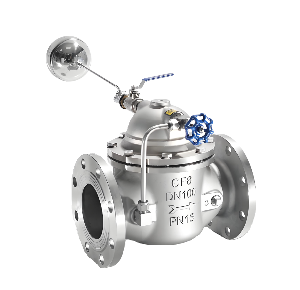
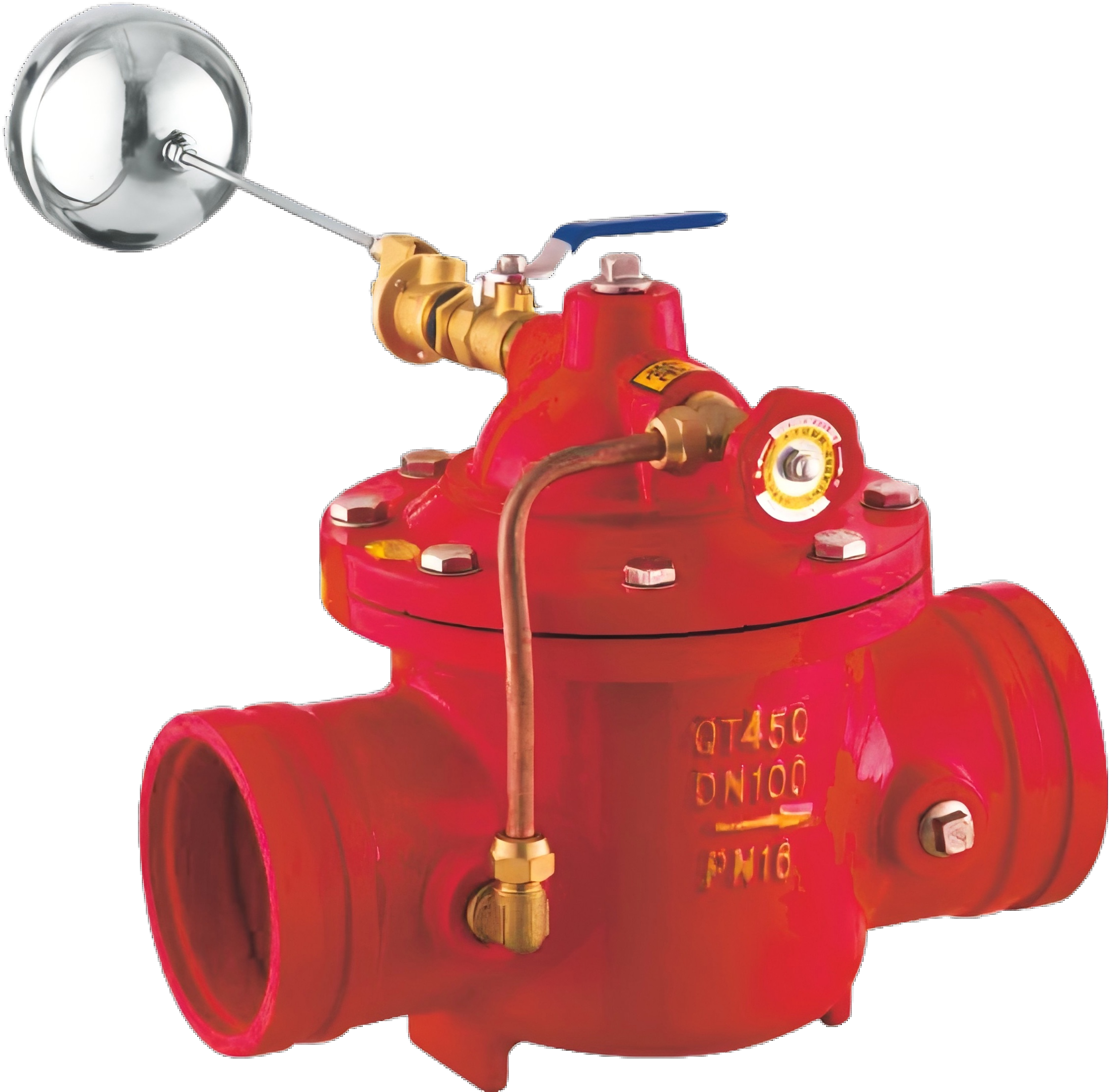
100X Remote Control Float Valve
Model:
100X-10/100X-16/100X-25/100X-10P/100X-16P/100X-25PSpecification:
DN350-DN800Pressure:
PN10~PN25Material:
Cast Iron.Stainless SteelProduct IntroductionThis product is designed and manufactured by our factory's engineers with reference to advanced domestic and foreign counterparts. It is commonly used in automatic water supply systems for water tanks and towers in high-rise buildings, industrial and mining enterprises, parks, etc. Features include compact size, light weight, easy installation and maintenance, and separable main valve and float valve. The valve body adopts a full-channel streamlined design, ensuring low fluid resistance, large flow rate, and excellent sealing performance. Equipped with a backflow pipe control system on the main valve, it realizes automatic operation via hydraulic power to control the liquid level of water towers or tanks. It offers simple maintenance, flexibility, durability, high level control accuracy, and tight closure without leakage, unaffected by water pressure. Welcome to purchase.Product Diagram of 100X Piston Type Remote Control Float ValveWorking PrincipleWhen water is supplied to the pipeline from the inlet end of the valve, since the needle valve 14, ball valve 8, and float valve 5 are normally open, water passes through the micro filter 13 and needle valve 14 into the valve cover control chamber, then flows into the water tank via the ball valve 8 and float valve 5. No pressure builds up in the control chamber, so the inlet pressure below the main valve disc lifts the main valve disc, allowing a large volume of water to flow into the tank.As the water level in the pool or water tower rises gradually, the float rises and closes the float valve 5. This causes water in the valve cover control chamber to gradually build up pressure until the main valve disc is closed, thereby achieving automatic remote control. When the water level drops to a certain point, the float descends with the water surface, opening the float valve. Water in the control chamber drains, pressure decreases, and the main valve disc is lifted to promptly replenish water in the pool or water tower.(This is the working principle of the diaphragm type, and the piston type operates similarly.)View detail>>
-
200X Piston Type Pressure Reducing Valve
Model:
200X-10/200X-16/200X-25/200X-10P/200X-16P/200X-25PSpecification:
DN350~DN800Pressure:
PN10~PN25Material:
Cast Iron, Cast Steel, Stainless Steel,CopperProduct IntroductionThis product is designed and manufactured by our professional technicians with reference to advanced counterparts from the US, France and domestic markets. It is suitable for industrial and mining enterprises, high-rise buildings, domestic water supply and fire protection systems. In scenarios requiring static and dynamic pressure reduction, it can replace intermediate water tanks, saving construction costs and expanding usable building space.The valve body features a full-channel streamlined design, ensuring low fluid resistance and large flow. It adopts hydraulic operation: water pressure in the pipeline automatically drives the main valve disc to move up and down, controlling the valve port opening and regulating downstream pressure to maintain it at the value set by the pilot valve spring. When downstream pressure exceeds the set value, the pressure reducing valve shuts off automatically. It delivers stable outlet pressure (P2) regardless of fluctuations in inlet pressure (P1) or changes in downstream flow. Additionally, the pilot valve allows a wide outlet pressure adjustment range (10-80% of the inlet pressure), with stable operation and no water hammer.200X Piston Type Pressure Reducing Valve Product DiagramWorking principleThe inlet pressure P1 enters the control chamber of the main valve through the conduit and needle valve 18 (see the structure diagram), establishing a downward pressure P3. The outlet pressure P2 also acts under the diaphragm (or piston) of the pilot valve via a conduit, opposing the regulating spring of the pilot valve. When the downstream pressure exceeds the set value of the pilot valve spring, the pilot valve closes, the water discharge from the control chamber becomes zero, the variable pressure P3 reaches its maximum, and the main valve disc is pressed tightly against the valve seat, closing the pressure reducing valve.Once the downstream pressure P2 drops below the set value of the pilot valve spring, the pilot valve opens, and the pressure water in the control chamber is discharged downstream through pilot valve 9 and ball valve 6. Due to the small opening of the needle valve and the smaller diameter of the inlet conduit compared to the outlet conduit, the discharge rate exceeds the water replenishment rate of the inlet pressure. As a result, the pressure P3 in the control chamber decreases, and the inlet pressure P1, which acts under the main valve disc, lifts the main valve disc, thereby opening the pressure reducing valve.In the stable regulation state, the discharge flow equals the replenishment flow, the opening of the main valve port remains unchanged, and the downstream pressure is stabilized. (This is the working principle of the diaphragm type, and the piston type works similarly.)View detail>>
-
300X Piston Type Slow-closing Check Valve
Model:
300X-10/300X-16/300X-25/300X-10P/300X-16P/300X-25PSpecification:
DN350~DN800Pressure:
PN10~PN25Material:
Cast Iron, Stainless SteelProduct IntroductionThis product is a new type of check valve developed by our factory's technicians with reference to advanced domestic and foreign counterparts. It features a novel structure, rational design, excellent sealing performance, low fluid resistance, large flow rate and long service life. Equipped with a duct control system on the main valve, it operates automatically via hydraulic power to achieve optimal opening/closing speeds, thereby preventing water hammer and water impact. It realizes slow-closing and noise reduction, making it an ideal choice for water supply systems in high-rise buildings. Welcome to purchase!300X Piston Type Slow-Closing Check Valve Product DiagramWorking PrincipleWhen the water pump starts operating, the water flow at the inlet end of the valve passes through the micro filter (16), needle valve (15), and check valve (14) into the control chamber of the valve cover, and then is discharged to the outlet through the ball valve (6). Since the opening of the needle valve (15) is small (usually 1/4 turn open is sufficient) and the diameter of the inlet pipe is smaller than that of the outlet pipe, the discharge speed in the control chamber is greater than the water supply speed at the inlet. As a result, the pressure in the control chamber decreases, and the inlet pressure acting under the main valve disc (5) lifts the main valve disc, thereby opening the main valve to supply water downstream.When the water supply stops, the water downstream starts to flow back. Due to the self-weight of the valve disc (5) and the pressure in the upper water chamber, the throttle port is quickly closed by 90%. The remaining 10% uses the pipe to transmit the pressure behind the valve to the upper water chamber. Due to the action of the check valve (14), the water in the upper water chamber cannot flow out, so the pressure in the water chamber gradually increases, and the valve stem moves down slowly, finally making the main valve disc close tightly. This prevents the backflow of downstream water and plays the role of slow closing and noise elimination. (This is the working principle of the diaphragm type, and the piston type is the same.)View detail>>
-
400X Piston Type Flow Control Valve
Model:
400X-10/400X-16/400X-25/400X-10P/400X-16P/400X-25PSpecification:
DN350~DN800Pressure:
PN10~DN25Material:
Cast Iron,Stainless SteelProduct IntroductionThis product, developed by our engineering and technical personnel through the introduction of new technologies as well as improvements in manufacturing processes and structures, has reached the advanced level of international similar products. The valve body adopts a full-channel streamlined design, featuring low fluid resistance and large flow rate. It uses hydraulic operation in terms of transmission mode, that is, the water pressure in the pipeline is utilized to automatically control the vertical movement of the main valve disc and adjust the opening of the main valve port. The main valve is installed in the pipeline for controlling flow in water supply and distribution pipelines. By presetting and adjusting the pilot regulating valve and a fixed flow rate of the pilot valve on the upper part of the valve, the flow rate through the main valve can be kept constant without being affected even if the pressure upstream of the main valve changes. In a word, this product is an ideal choice for domestic water supply, fire protection systems and industrial water supply systems.400X Piston Type Flow Control Valve Product DiagramWorking PrincipleWhen the water pressure at the inlet of the main valve enters the valve body and the control chamber (see the structure diagram) respectively, and the ball valve 6 outside the main valve is closed at the same time, the main valve is in a fully closed state. When the ball valve 6 outside the main valve is fully opened, all the water pressure in the control chamber is discharged to the low-pressure area downstream, and the main valve is in a fully open state. Adjust the opening degree of the ball valve 6 outside the main valve to balance the water flow through the needle valve 17 and the ball valve 6, and the main valve is in a floating state.The flow control valve uses the pressure difference of water flow entering the main valve control chamber through the conduit and the needle valve 17, leads the pipe to and controls the valve opening degree by means of the spring of the adjusting conduit 9, and adjusts the pilot regulating valve 15 on the upper part of the main valve to ensure the set opening degree of the main valve port, so that the flow in the pipeline does not exceed a certain set value. Even if the upstream pressure changes, it will not affect the downstream pressure. (This is the working principle of the diaphragm type, and the same applies to the piston type.)View detail>>
-
500X Piston Type Pressure Relief/Sustaining Valve
Model:
500X-10/500X-16/500X-25/500X-10P/500X-16P/500X-25PSpecification:
DN350~DN800Pressure:
PN10~PN25Material:
Cast Iron, Stainless SteelProduct IntroductionThis valve is a new-type product developed by our engineering technicians with reference to advanced counterparts from the US, France and domestic markets. It adopts hydraulic operation and automatic control via pressure difference in the control pipeline to automatically open/close and shut off the main valve, ensuring upstream pressure does not exceed a set value.The valve body features a full-channel streamlined design, offering low fluid resistance, excellent sealing performance and sensitive automatic opening/closing response. Its key advantage is dual functionality as both a pressure relief valve and a pressure sustaining valve:As a pressure relief valve, it releases pressure in water supply pipelines exceeding the pilot valve’s safe set value, maintaining pressure below the safe threshold to prevent pipeline/equipment damage from overpressure or sudden pressure surges. It is applicable to fire test circulation systems in high-rises and other water supply systems to avoid system risks from excessive water pressure.As a pressure sustaining valve, it maintains upstream water supply pressure above a set value to ensure stable pressure in upstream supply areas, mainly for urban low-pressure water supply zones.In summary, it is an ideal product for water supply systems. Welcome to purchase.500X Piston Type Pressure Relief/Sustaining Valve Product DiagramWorking Principle and ApplicationWhen used as a pressure relief valve, the main valve is installed in the drainage bypass, i.e., in parallel with the main pipeline. When the upstream pressure gradually rises above the set value of pilot valve 13, the main valve opens quickly to drain water and reduce pressure. It only closes slowly and smoothly when the upstream pressure drops below the set value of pilot valve 13, avoiding water hammer and ensuring the safety of the pipeline. When functioning as a pressure relief valve, it is mainly used to eliminate excessively high pressure that gradually increases due to supply exceeding demand, such as in the initial stage of fire fighting in fire hydrant systems, automatic sprinkler systems, and at the outlet of water pumps in various water supply systems. When used as a pressure relief valve, ball valve 12 is normally open.When used as a pressure retaining valve, the main valve is installed on the main pipeline, i.e., in series with the main pipeline. The main valve remains closed as long as the water supply pressure upstream of the main valve is lower than the set value of pilot valve 13. It will automatically open to supply water to the downstream when the upstream pressure exceeds the set value of pilot valve 13, thus ensuring the water supply pressure upstream of the main valve. It is mainly used to maintain the minimum water supply pressure of urban main pipes. Especially in case of fire, it can prevent branch users from excessive water pumping which would reduce the pressure. When used as a pressure retaining valve, ball valve 12 is normally closed or replaced with a pipe plug.View detail>>
-
600X Piston-type Hydraulic Electric Control Valve
Model:
600X-10/600X-16/600X-25/600X-10P/600X-16P/600X-25PSpecification:
DN350~DN800Pressure:
PN10~PN25Material:
Cast Iron, Stainless SteelProduct IntroductionThis product is designed and manufactured by the engineering and technical personnel of our unit with reference to advanced similar products at home and abroad. The valve body adopts a streamlined design, featuring small fluid resistance, large flow rate and excellent sealing performance. Equipped with a pipe control system with a solenoid valve as the pilot valve on the main valve, it uses hydraulic operation and is often used for automatic control in water supply, drainage and industrial systems. It is a valve that can be remotely controlled to open and close, and a speed control device can be added if needed. It can replace large electric devices for opening and closing gate valves and butterfly valves, with the advantages of small size, light weight, simple maintenance, convenient use, safety and reliability. Welcome to purchase!600X Piston-type Hydraulic Electric Control Valve Product DrawingWorking PrincipleWhen the water pump starts operating, the water flow at the inlet end of the valve passes through the micro filter, needle valve 14, pressure control chamber, electromagnetic pilot valve 8, ball valve 6 in sequence, and is discharged to the outlet. At this time, the electromagnetic pilot valve is energized (the solenoid valve works synchronously with the water pump motor) and remains in a normally open state. Due to the small opening of needle valve 14 and the smaller diameter of the inlet pipe compared to the outlet pipe, the discharge speed in the control chamber is greater than the water replenishment speed. As a result, the pressure in the control chamber decreases, and the inlet pressure acting under the main valve disc lifts the main valve disc, thereby opening the main valve to supply water downstream.When water supply needs to be stopped, the water pump motor shuts down, and the electromagnetic pilot valve 14 closes due to power failure (normally closed state). Since the downstream water starts to flow back and the self-weight of the valve disc causes the throttle port to close quickly by 90%, the remaining 10% uses the pipe to transmit the pressure behind the valve to the upper water chamber. Due to the action of the electromagnetic pilot valve, the pressure in the upper water chamber gradually increases, eventually causing the main valve disc to close tightly. This prevents downstream water from flowing back, protects the water pump motor, and also plays a role in slow closing and noise elimination. (This is the working principle of the diaphragm type, and the piston type works similarly.)View detail>>
-
700X Piston Pump Control Valve
Model:
700X-10/700X-16/700X-25/700X-10P/700X-16P/700X-25PSpecification:
DN350~DN800Pressure:
PN10~PN25Material:
Cast Iron,Ductile Iron,Carbon Steel,Stainless SteelProduct IntroductionThis product is designed and manufactured by our factory's engineers with reference to advanced domestic and foreign similar products. The valve body features a streamlined design, ensuring low fluid resistance, large flow rate, and excellent sealing performance. Equipped with a solenoid valve-guided pipeline control system, it operates hydraulically and is commonly used for automatic control in water supply, drainage, and industrial systems, enabling remote operation of valve opening and closing. It can be additionally fitted with a speed control device. This product replaces large electric devices for gate valves and butterfly valves, offering advantages such as small size, light weight, easy maintenance, convenient operation, safety, and reliability. Welcome to purchase!Product diagram of 700X Piston Pump Control ValveWorking PrincipleWhen the water pump starts operating, the water flow at the inlet end enters the valve cover control chamber through needle valve 3 and check valve 1, and then is discharged to the outlet through check valve 2, solenoid pilot valve 7, and ball valve 8. When the valve disc opens to 10%, it touches the electrical control switch, at which point the solenoid pilot valve is energized and remains in a normally closed state. Due to the small opening of needle valve 3 (usually 1/4 turn open) and the smaller diameter of the inlet pipe compared to the outlet pipe, the discharge speed in the control chamber is higher than the water replenishment speed. As a result, the pressure in the control chamber decreases, and the inlet pressure lifts the main valve disc to supply a large amount of water downstream. When water supply needs to be stopped, before the water pump shuts down, the inlet pressure first closes 90% of the main valve. At this time, the solenoid pilot valve 7 is in a normally open state due to power failure. For the remaining 10%, the pressure in the upper water chamber gradually increases through the action of solenoid pilot valve 7 and check valves 1 and 2, eventually closing the main valve disc tightly. This can completely prevent water hammer, protect the water pump motor, and also achieve slow closing and noise reduction.View detail>>
-
900X Piston Emergency Shut-off Valve
Model:
900X-10/900X-16/900X-25/900X-10P/900X-16P/900X-25PSpecification:
DN350~DN800Pressure:
PN10~PN25Material:
Cast Iron, Stainless SteelProduct IntroductionThis product is designed and manufactured by our factory's engineering and technical personnel with reference to advanced products of the same type from the United States, France and other countries. It is suitable for parallel water supply systems in industrial enterprises, domestic water supply and fire water supply. During fire water supply, the valve automatically closes urgently to cut off domestic water supply and ensure fire water demand. After the fire is extinguished, the valve automatically opens to resume domestic water supply. It can replace the intermediate water tank in occasions requiring static pressure and dynamic pressure reduction, saving the cost of building intermediate water tanks and expanding the usable space of buildings. The valve body adopts a full-channel streamlined design, featuring low fluid resistance and large flow rate. Hydraulic operation is adopted for the transmission method—utilizing the water pressure in the pipeline to automatically drive the main valve disc up and down, control the valve port opening, adjust the downstream pressure, and maintain the downstream pressure at the set value of the pilot valve spring. When the downstream pressure exceeds the set value, the pressure reducing valve will automatically close. Regardless of fluctuations in the inlet pressure P1, a stable outlet pressure P2 can be output. It can adapt to downstream flow changes ranging from 10% to 80% of the inlet pressure, operating stably without water hammer impact.900X Piston Emergency Shut-off Valve Product DrawingWorking PrincipleWhen fire water is used, open Ball Valve 19 and close Ball Valve 6 (see the structural diagram). Under the action of reverse pressure, when the pressure below the diaphragm of the pilot valve exceeds the spring setting value above the pilot valve, the pilot valve closes. Due to the function of the check valve, the water discharge volume in the control chamber is 0, and the main valve will automatically close to cut off domestic water supply and ensure fire water supply. When the fire fighting is completed, close Ball Valve 19 and open Ball Valve 6, the valve will automatically open to resume domestic water supply. Inlet pressure P1 enters the control chamber of the main valve through the conduit and needle valve, and establishes downward pressure P3. Outlet pressure P2 also acts under the diaphragm (or piston) of the pilot valve through the conduit and opposes the regulating spring of the pilot valve. When the variable pressure P3 reaches the maximum value, the main valve disc is pressed tightly against the valve seat and the pressure reducing valve closes. Once the downstream pressure P2 drops to the pilot valve spring setting value, the pilot valve opens, and the pressure water in the control chamber will be discharged to the downstream through Pilot Valve 9 and Ball Valve 6. Due to the small opening of the needle valve and the smaller diameter of the inlet conduit than the outlet conduit, the discharge speed is greater than the inlet pressure water supplement speed, thus the pressure P3 in the control chamber decreases. The inlet pressure P1 acting under the main valve disc will lift the main valve disc, thereby opening the pressure reducing valve. In the stable regulation state, the discharge flow is equal to the water supplement flow, the opening of the main valve port remains unchanged, and the downstream pressure is stable. (This is the working principle of the diaphragm type, and the piston type is the same.)View detail>>
-
H142X Hydraulic Water Level Control Valve
Model:
H142X-6/H142X-10/H142X-16/H142X-25/H142X-6P/H142X-10P/H142X-16P/H142X-25PSpecification:
DN40~DN350Pressure:
PN6~PN25Material:
Cast Iron, Stainless SteelProduct IntroductionThe H142X hydraulic water level control valve product is suitable for automatic water supply systems of various water tanks, water pools, and water towers in industrial and mining enterprises and civil buildings, and can be used as a circulating water control valve for atmospheric boilers.H142X Hydraulic Water Level Control Valve Product DiagramWorking PrincipleWhen the water level in the pool or water tower drops, the float valve opens, causing the upper chamber of the piston to lose pressure. The pressurized water in the inlet pipe lifts the piston inside the valve, and the valve disc opens, opening the valve for water supply. When the water level rises to the control line, the float valve closes, and the pressurized water in the upper chamber of the piston pushes the piston down to close the sealing surface, stopping the water supply to the valve.View detail>>
-
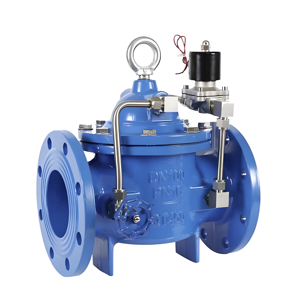
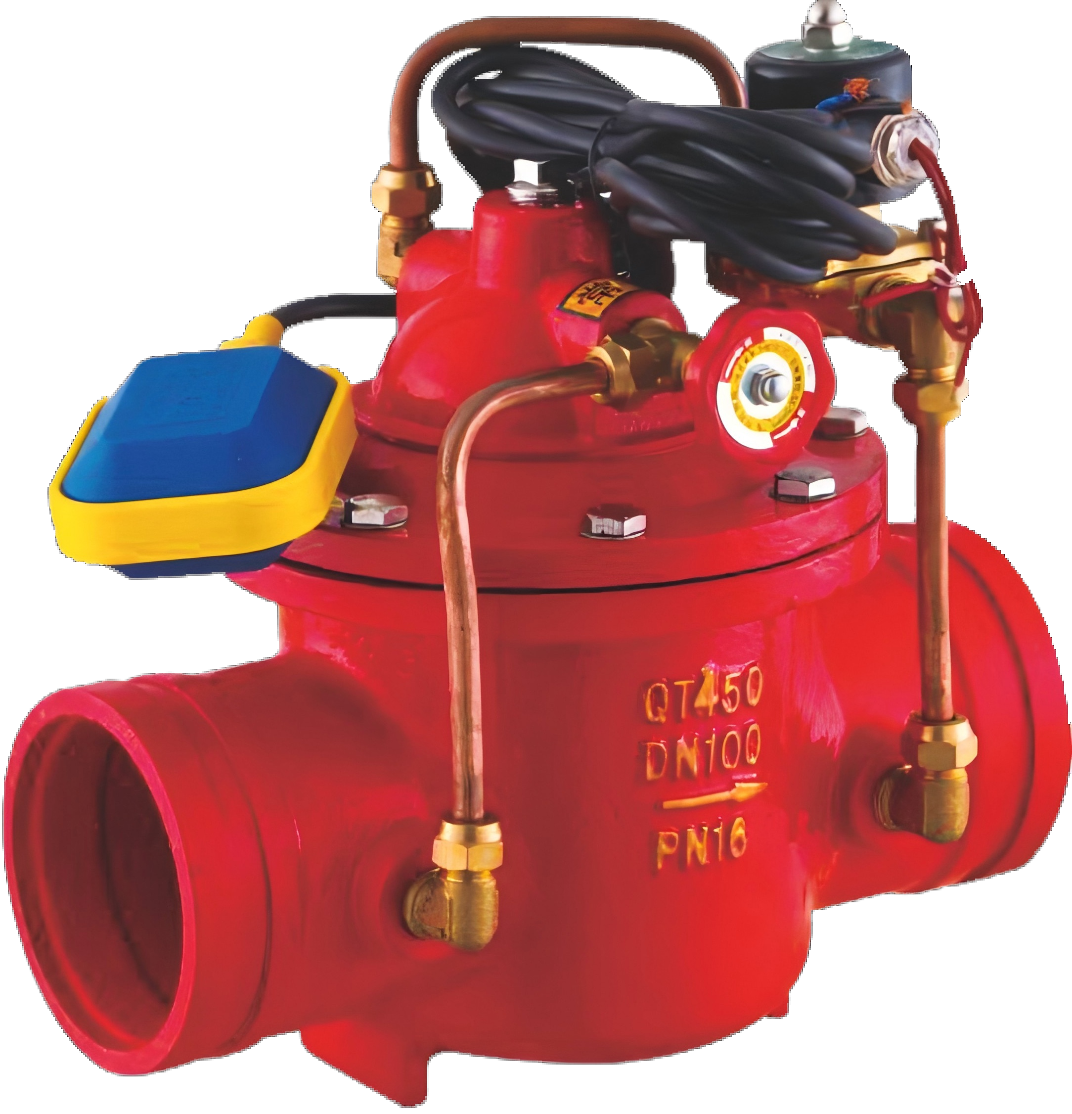
J145X Electric Remote Control Valve
Model:
J145X-10/J145X-16/J145X-25/J145X-10P/J145X-16P/J145X-25PSpecification:
DN50~DN1000Pressure:
PN10~PN25Material:
Cast Iron, Stainless SteelApplicationThe J145X Electric Remote Control Valve produced by our company is mainly used to be installed in the pipelines of high-rise building water supply systems and other water supply systems. It opens or closes the valve according to electrical signals or manual operation, and can replace large-scale electric devices used to open and close gate valves or butterfly valves.J145X Electric Remote Control Valve Product DiagramWorking PrincipleThrough pressure transmission via the hydraulic conduit, the main valve slide plate (valve disc) mimics the action of the pilot valve. When the electrical signal is an opening command, the solenoid valve opens to release the pressure water above the diaphragm, and the main valve opens. When the electrical signal is a closing command, the solenoid pilot valve closes, and the upstream pressure acts on the top of the diaphragm to close the main valve.View detail>>
-
AX742X Safety Relief/Pressure Retaining Valve
Model:
AX742X-10/AX742X-16/AX742X-25/AX742X-10P/AX742X-16P/AX742X-25PSpecification:
DN50~DN1000Pressure:
PN10~PN25Material:
Cast Iron, Stainless SteelApplication The AX742X Safety Relief/Pressure Retaining Valve produced by our company is mainly installed in the pipelines of high-rise buildings, fire water supply systems and other water supply systems. When the pressure in the water supply pipeline exceeds the set pressure of the relief valve, the relief valve automatically opens to release pressure quickly, protecting the safety of the pipeline. It can also be used as a pressure retaining valve to ensure the water supply pressure upstream of the main valve.AX742X Safety Pressure Relief/Sustaining Valve Product DiagramFeatures1.It can accurately maintain a constant safe set pressure. Once overpressure occurs, the relief valve opens quickly to release pressure in a timely manner.2.The closing is smooth and reliable, eliminating pressure afterwaves and water hammer.View detail>>
-
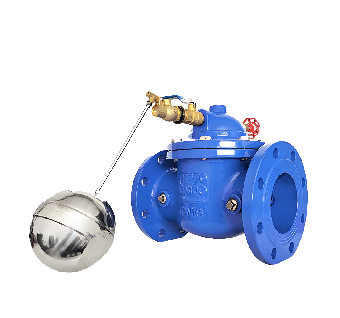
Model F745X Remote Control Float Valve
Model:
F745X-10/F745X-16/F745X-25/F745X-10P/F745X-16P/F745X-25PSpecification:
DN50~DN1000Pressure:
PN10~PN25Material:
Cast Iron, Stainless SteelApplicationThe Model F745X Remote Control Float Valve produced by our company is mainly installed in the water inlet pipelines of various water tanks and water towers in industrial enterprises and civil buildings. It automatically closes when the water tank reaches the preset water level and opens automatically to replenish water when the water level drops.Product Diagram of F745X Remote Control Float ValveFeatures1.Tight and reliable closure: Equipped with a robust rubber sealing ring, it adopts the hydraulic control principle, making the sliding plate closing force proportional to the water pressure for high sealing reliability.2.Large flow capacity: The valve body features a full-channel streamlined design, ensuring low fluid resistance and large flow rate.3.Easy operation and maintenance: The main valve is installed outside the water tank, enabling convenient commissioning, inspection and simple maintenance.View detail>>
-
F8745X groove fire pump control valve
Model:
F8745X-10/F8745X-16/F8745X-10Q/F8745X-16Q/F8745X-10P/F8745X-16P/F8745X-10T/F8745X-16TSpecification:
DN50-DN1000Pressure:
PN10~PN16Material:
Cast iron, ductile iron, stainless steel, copperOverviewThe F8745X groove fire pump control valve is a specialized control valve developed by our factory in accordance with national fire safety regulations and combined with the high reliability requirements of modern fire protection systems. This valve integrates multiple fire core functions such as hydraulic automatic control, slow start and fast stop of water pumps, anti backflow and water hammer elimination, emergency linkage control, etc. It is designed specifically for the safety guarantee of the outlet pipeline of fire pump groups. The valve adopts a groove type connection, which is easy and efficient to install. At the same time, a mature piston type hydraulic control structure is used, and an adjustable hydraulic damping device is built-in to achieve smooth and gradual opening of the water pump during startup and rapid segmented closing during emergency shutdown. It effectively absorbs and eliminates the high-pressure water hammer impact unique to the fire protection system, protecting the safety of the water pump and pipeline network. This valve does not require external power drive and relies entirely on system water pressure for intelligent control. It responds quickly and operates reliably, making it particularly suitable for key fire water supply pipelines such as fire hydrant systems, automatic sprinkler systems, and fire stabilization systems. This product has outstanding advantages such as sturdy structure, sensitive action, easy maintenance, and compliance with fire certification. It is the core control equipment that ensures the reliable standby state of the fire water supply system at all times. Welcome to consult and purchase.F8745X groove fire pump control valve product diagramfeatureThe working principle of the F8745X groove fire pump control valve is based on hydraulic control and piston differential pressure principle, designed specifically for high reliability requirements of fire protection systems. The valve is automatically controlled by the system's own water pressure drive, mainly composed of a main valve body, a piston actuator, a pilot control valve group, and a multifunctional regulating module. Its core operating mechanism is divided into three stages: when the fire pump is started, the system pressure water enters the upper chamber of the piston through the diversion control pipeline, and the downward speed of the piston is controlled by a precisely adjusted damping device to achieve smooth and gradual opening of the valve, avoid pressure shock in the pipeline network, and protect the fire protection motor; During the normal operation of fire water supply, the valve should be kept fully open to ensure smooth water flow and meet the maximum flow and pressure requirements of the system; When the pump is stopped or the power is cut off due to an accident, the pressure at the front end of the valve drops sharply, triggering the action of the control mechanism. The pressure water in the upper chamber of the piston is discharged through the quick release channel. The valve disc quickly closes to the set angle under the action of the main return water pressure (quick closing stage), and then the final sealing is completed through an independently adjustable slow closing resistance device (slow closing stage). This graded closing process can efficiently eliminate the high-pressure water hammer unique to the fire protection system and prevent damage to the pipeline network and equipment. The entire process relies entirely on hydraulic automation, without the need for external power or gas sources, meeting the high reliability requirements of firefighting equipment.View detail>>
-
G100X remote control floating ball valve for groove
Model:
G100X-10/G100X-16/G100X-10Q/G100X-16Q/G100X-10P/G100X-16P/G100X-10T/G100X-16TSpecification:
DN50-DN200Pressure:
PN10~PN16Material:
Cast iron, ductile iron, stainless steel, copperOverviewGroove type (clamp) connection valves are a series of new connection valves designed and manufactured by introducing advanced products of the same type from the United States and Germany. It has the advantages of fast, simple, safe, reliable installation, no restrictions on installation site, easy maintenance of pipelines and valves, vibration isolation and sound insulation, overcoming the distortion caused by different axes of pipeline connections within a certain angle range, and solving the thermal expansion and contraction caused by temperature differences. G100X groove remote control floating ball valve product diagramfeatureThe groove type hydraulic control valve is a valve controlled by water pressure, which consists of a main valve and its attached pipes, guide valves, needle valves, ball valves, and pressure gauges. According to different usage purposes, functions, and locations, it can be evolved into remote control float valves, pressure reducing valves, slow closing check valves, flow control valves, pressure relief valves, hydraulic electric control valves, etc. The working principle is the same, both are powered by a pressure difference of 4P between upstream and downstream, controlled by a pilot valve, to enable diaphragm hydraulic differential operation, fully regulated by hydraulic automatic control, so that the main valve disc can be fully opened or fully closed or in a regulating state. When the pressure water entering the control room above the diaphragm is discharged to the atmosphere or downstream low-pressure area, the pressure value acting on the bottom of the valve disc and below the diaphragm is greater than the pressure value above, so push the main valve disc to the fully open position; When the pressure water entering the control chamber above the diaphragm cannot be discharged to the atmosphere or downstream low-pressure area, the pressure value acting above the diaphragm is greater than the pressure value below, so the main valve disc will be pressed to the fully closed position; When the pressure value in the control chamber above the diaphragm is between the inlet pressure and the outlet pressure, the main valve disc is in a regulating state, and its regulating position depends on the joint control effect of the needle valve and the adjustable pilot valve in the conduit system. Adjustable pilot valves can open or close their own small valve ports according to the downstream outlet pressure, thereby changing the pressure value controlled above the diaphragm and controlling the adjustment position of the main valve disc.View detail>>
-
G106X groove hydraulic electric floating ball control valve
Model:
G106X-10/G106X-16/G106X-10Q/G106X-16Q/G106X-10P/G106X-16P/G106X-10T/G106X-16TSpecification:
DN50-DN600Pressure:
PN10~PN16Material:
Cast iron, ductile iron, stainless steel, copperOverviewThe G106X groove type hydraulic electric floating ball control valve is a new type of control valve designed and manufactured by introducing advanced technology from similar products in the United States and Germany. It adopts a groove type (clamp) connection method, which is fast, easy, safe, reliable to install, not limited by installation site, easy to maintain pipelines and valves, can isolate vibration and sound insulation, and can overcome the deviation caused by different axes of pipeline connection within a certain angle range, effectively solving the problem of thermal expansion and contraction caused by temperature difference. This valve integrates electric actuator and float control functions, mainly used for automatic liquid level control in water conservancy systems, achieving intelligent management of water supply, drainage and other processes. Product Image of G106X Grooved Hydraulic Electric Float Control ValvefeatureThe G106X groove type hydraulic electric float control valve is a valve controlled by water pressure. It consists of a main valve and its attached conduit, an electric float switch (as a signal pilot valve), a needle valve, a ball valve, and a pressure gauge. This valve belongs to a specific application of hydraulic control valves, which can be evolved into remote control float valves, pressure reducing valves, slow closing check valves, flow control valves, pressure relief valves, hydraulic electric control valves, etc. depending on the purpose, function, and location of use. The working principle is the same, both are powered by the upstream and downstream pressure difference Δ P, jointly controlled by an electric float switch and a pilot valve, allowing for diaphragm hydraulic differential operation, fully regulated by hydraulic automatic control, thereby fully opening or closing the main valve disc. When the electric float switch detects a low liquid level and opens the pilot valve, the pressure water entering the control room above the diaphragm is discharged to the atmosphere or downstream low-pressure area. The pressure value acting on the bottom of the valve disc and below the diaphragm is greater than the pressure value above, so the main valve disc is pushed to the fully open position for water replenishment; When the electric float switch detects a high liquid level and closes the pilot valve, the pressure water entering the control room above the diaphragm cannot be discharged to the atmosphere or downstream low-pressure area. The pressure value acting above the diaphragm is greater than the pressure value below, so the main valve disc will be pressed to the fully closed position to stop water supply. By using an electric float switch to accurately sense changes in liquid level and control the pilot valve, hydraulic automatic control based on liquid level has been achieved.View detail>>
-
G200X fire pressure reducing valve
Model:
G200X-10/G200X-16/G200X-10Q/G200X-16Q/G200X-10P/G200X-16P/G200X-10T/G200X-16TSpecification:
DN50-DN200Pressure:
PN10~PN16Material:
Cast iron, ductile iron, stainless steel, copperOverviewG200X fire pressure reducing valve is a specialized pressure reducing and stabilizing valve designed and manufactured with advanced international hydraulic control technology. It adopts a groove type (clamp) connection, which has the characteristics of fast, easy, safe, and reliable installation. This valve is mainly used in fire water supply systems and other water supply pipelines that require pressure reduction. It can reduce the high inlet pressure to a stable and satisfactory outlet pressure, and automatically adjust when the flow rate changes to maintain a basically constant outlet pressure, thereby ensuring that end devices such as fire sprinklers and alarm valves work normally under the specified pressure, avoiding overpressure damage, and ensuring the safety and reliability of the fire protection system operation. Its compact structure, easy maintenance, and unrestricted installation site make it an indispensable key control equipment in modern fire engineering. G200X Fire Pressure Relief Valve Product Diagram featureThe throttling position of the main water pressure reducing valve is controlled by an adjustable pilot valve operated in conjunction with a needle valve. The pilot valve senses the downstream (outlet) pressure and immediately reacts, repositioning its piston to increase or decrease the outlet pressure with different demands. The change in the throttle position of the pilot valve piston will cause a change in the flow control water, which will alter the pressure above the diaphragm of the main valve, thereby repositioning the diaphragm assembly and throttling of the main valve to maintain the desired preset reduction in outlet pressure.View detail>>
-
G300X groove slow closing check valve
Model:
G300X-10/G300X-16/G300X-10Q/G300X-16Q/G300X-10P/G300X-16P/G300X-10T/G300X-16TSpecification:
DN50-DN200Pressure:
PN10~PN16Material:
Cast iron, ductile iron, stainless steel, copperOverviewThe G300X slow closing check valve is a high-performance control valve independently developed and manufactured by our factory based on the introduction of advanced technology from Europe and America, combined with domestic working conditions. It integrates the functions of electric valve, check valve, and water hammer eliminator, and can effectively achieve integrated automatic control of pump unit opening, slow closing, and check. This valve can effectively eliminate the water hammer hazard caused by medium backflow and rapid changes in flow rate during pump shutdown, protecting the safety of the pump and pipeline system. The valve adopts a unique dual chamber and pilot valve control system, which achieves smooth and impact free closure by adjusting the slow closing time and angle. It is particularly suitable for water pump outlet pipelines in high-rise buildings, industrial and mining enterprises, municipal water supply and fire protection systems. This valve has the advantages of low flow resistance, reliable operation, easy maintenance, and significant anti backflow and water hammer elimination effects. It is a key equipment to ensure the safe and stable operation of long-distance and high head water conveyance systems. Welcome to consult and purchase. G300X groove slow closing check valve product diagram featureThe working principle of G300X slow closing check valve is to use the pressure and flow rate changes of the medium itself in the pipeline as the control power, and achieve automatic and phased closure of the valve disc through a pilot control system. When the water pump is running normally, the medium pressure pushes the valve disc to fully open; At the moment when the water pump suddenly stops, the valve disc begins to quickly close to about 80% -90% opening under the action of medium reflux and spring. At this time, the valve enters the preset slow closing stage. By accurately controlling the closing speed of the remaining opening through an independent regulating valve, the medium slowly flows back, effectively eliminating the destructive water hammer pressure caused by sudden flow rate changes and achieving smooth protection of the water pump and pipeline system.View detail>>
-
G500X groove pressure relief valve
Model:
G500X-10/G500X-16/G500X-10Q/G500X-16Q/G500X-10P/G500X-16P/G500X-10T/G500X-16TSpecification:
DN50-DN200Pressure:
PN10~PN16Material:
Cast iron, ductile iron, stainless steel, copperOverviewThe G500X groove pressure relief valve is a key safety protection valve independently developed and produced by our factory based on the digestion and absorption of international advanced technology, combined with the actual working conditions in China. It integrates the functions of a safety valve, a pressure relief valve, and a pressure regulating valve, and can reliably achieve comprehensive control of system overpressure automatic release, pressure stability, and safety protection. This valve can effectively eliminate abnormal pressure increases in the system caused by pump unit start stop, valve misoperation, or temperature changes, avoiding damage to pipelines and equipment due to overpressure. The valve adopts a pilot controlled structure and a precision pressure feedback system, which dynamically monitors and automatically adjusts the pipeline pressure by setting precise discharge pressure and continuous discharge flow rate. It is particularly suitable for pressure protection of high-rise building water supply systems, fire water supply networks, industrial circulating water systems, and long-distance water transmission pipelines. This valve has the advantages of sensitive response, accurate pressure relief, stable operation, reliable reset, and easy maintenance. It is an important device to ensure the safe, stable, and long-term operation of various pressure pipeline systems. Welcome to consult and purchase. G500X groove pressure relief valve product diagram featureThe working principle of G500X groove pressure relief valve is to use the change of pressure in the sensing pipeline system as the control signal, and use the pilot pressure feedback system to drive the opening and closing action of the main valve. When the pressure inside the pipeline is within the normal set range, the main valve remains closed; When the system pressure rises due to reasons and exceeds the preset safety value, the pilot valve automatically opens, releasing the pressure in the control chamber of the main valve, causing the main valve disc to quickly open under the pressure of the medium, and discharging excess medium in an orderly manner to the low-pressure side or atmosphere, thereby achieving rapid pressure relief. When the system pressure returns to below the safe set value, the pilot valve will automatically close, the control chamber will rebuild pressure, and the main valve will be driven to close smoothly. This process achieves overpressure protection and pressure stability control of the pipeline system through continuous pressure monitoring and dynamic adjustment, ensuring that the pipeline network and equipment always operate within a safe pressure range.View detail>>
-
G600X groove hydraulic electric control valve
Model:
G600X-10/G600X-16/G600X-10Q/G600X-16Q/G600X-10P/G600X-16P/G600X-10T/G600X-16TSpecification:
DN50-DN200Pressure:
PN10~PN16Material:
Cast iron, ductile iron, stainless steel, copperOverviewThe G600X groove hydraulic electric control valve is a high-performance integrated control valve independently developed by our factory for complex working conditions in China, based on the integration of international advanced control technology. It integrates the functions of electric actuators, hydraulic control valves, and intelligent regulating valves, and can achieve intelligent comprehensive management of remote electric control, precise flow regulation, and system pressure stability. This valve drives the hydraulic control main valve through the electric actuator, which not only retains the characteristics of rapid response and reliable operation of the hydraulic control valve, but also has the advantages of accurate and convenient electric control and remote integration, effectively solving the problems of insufficient adjustment accuracy and delayed response of traditional valves in the automation system. The valve adopts a modular design, equipped with high-precision position feedback and pressure compensation system, which can achieve precise setting and automatic maintenance of flow and pressure according to system requirements. It is particularly suitable for regional water supply systems, central air conditioning water systems, industrial process control, and intelligent building automation systems. This valve has the advantages of high control accuracy, fast response speed, low operating energy consumption, strong adaptability, and support for multiple communication protocols. It is a key equipment to promote the upgrading of traditional fluid control systems to intelligence and automation. Welcome to consult and purchase. G600X groove hydraulic electric control valve product diagram featureThe working principle of the G600X groove hydraulic electric control valve is to achieve a dual control mode combining electrical signal instructions and hydraulic drive by integrating an electric actuator and a hydraulic control valve. Its core consists of electric actuators, hydraulic main valves, and intelligent control modules, which can accurately adjust the valve opening based on external control signals (such as PLC instructions, remote switch signals, or analog signals) or preset programs. When the electric actuator receives the control signal, it drives the control chamber regulating device of the hydraulic main valve, changes the pressure state in the control chamber, and thus drives the valve disc of the main valve to move to the corresponding opening position. The position sensor embedded in the valve provides real-time feedback on the position of the valve disc, forming a closed-loop control to ensure the accuracy of the opening. At the same time, the hydraulic control system can independently respond to changes in pipeline pressure and provide auxiliary stabilizing or slow closing functions. This design ensures the accuracy and automation level of electric control, while retaining the advantages of fast response and fault safety of hydraulic control (which can rely on hydraulic characteristics to achieve protective actions in case of power loss). It realizes intelligent and high-precision regulation of flow and pressure, and is suitable for complex fluid systems that require precise control and automation management.View detail>>
Address:No. 1, Linxia Road, Sanqiao Industrial Zone, Oubei Sub-district, Yongjia County, Zhejiang Province| Switchboard:0577-67198981| mobile:+8613388552747| Email:sales@shanliuvalve.com|
COPYRIGHT © Zhejiang Shanliu Valve Technology Co., Ltd. Main Business: Water Valve Industrial valve|
浙ICP备2026020749号![]()