Your location:
 /
valves
/
More water supply and drainage valves
/
Hydraulic Control Valve
/
400X Diaphragm Type Flow Control Valve
/
valves
/
More water supply and drainage valves
/
Hydraulic Control Valve
/
400X Diaphragm Type Flow Control Valve

Mark Classification of Fluid products
- Phone:+86(577)67198981
- Fax:+86(577)67038872
- mobile:+8613388552747
- Sales Email 1:Karrie@shanliuvalve.com
- Sales Email 2:Yannie@shanliuvalve.com
- Sales Email 3:Merry@shanliuvalve.com
- Sales Email 4:Lucas@shanliuvalve.com
- Email:sales@shanliuvalve.com


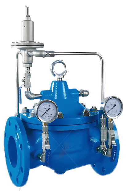
400X Diaphragm Type Flow Control Valve
- Model:400X-10/400X-16/400X-25/400X-10P/400X-16P/400X-25P
- Specification:DN50~DN400
- Temperature:≤80℃
- Medium:Water, sewage, seawater, and media similar to water.
- Pressure:PN10~PN25
- Connection method:flange
- Driving method:Spring, automatic
- Material:Cast iron, stainless steel,


Add QR code to serve you!
- Product Overview
- Performance Data
- Size Weight
Product Introduction
This product has reached the advanced level of international similar products through the introduction of new technologies, manufacturing processes, and structural improvements by our engineering and technical personnel. The valve body adopts a full channel streamline design, with low fluid resistance and high flow rate. Hydraulic operation is adopted in the transmission mode, which uses the water pressure in the pipeline to automatically operate the up and down movement of the main valve disc and control the opening of the main valve port. The main valve is installed in the pipeline of the water supply and distribution pipeline to control the flow rate. You can first set a fixed flow rate for the upper guide regulating valve and the guide valve to keep the flow through the main valve constant, even if the pressure upstream of the main valve changes, it will not affect it. In short, this product is an ideal choice for domestic water supply, fire protection systems, and industrial water supply systems.
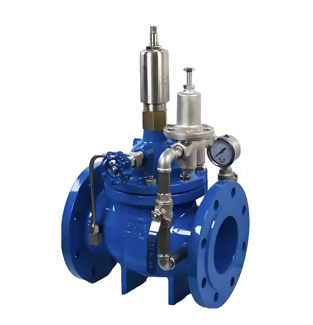
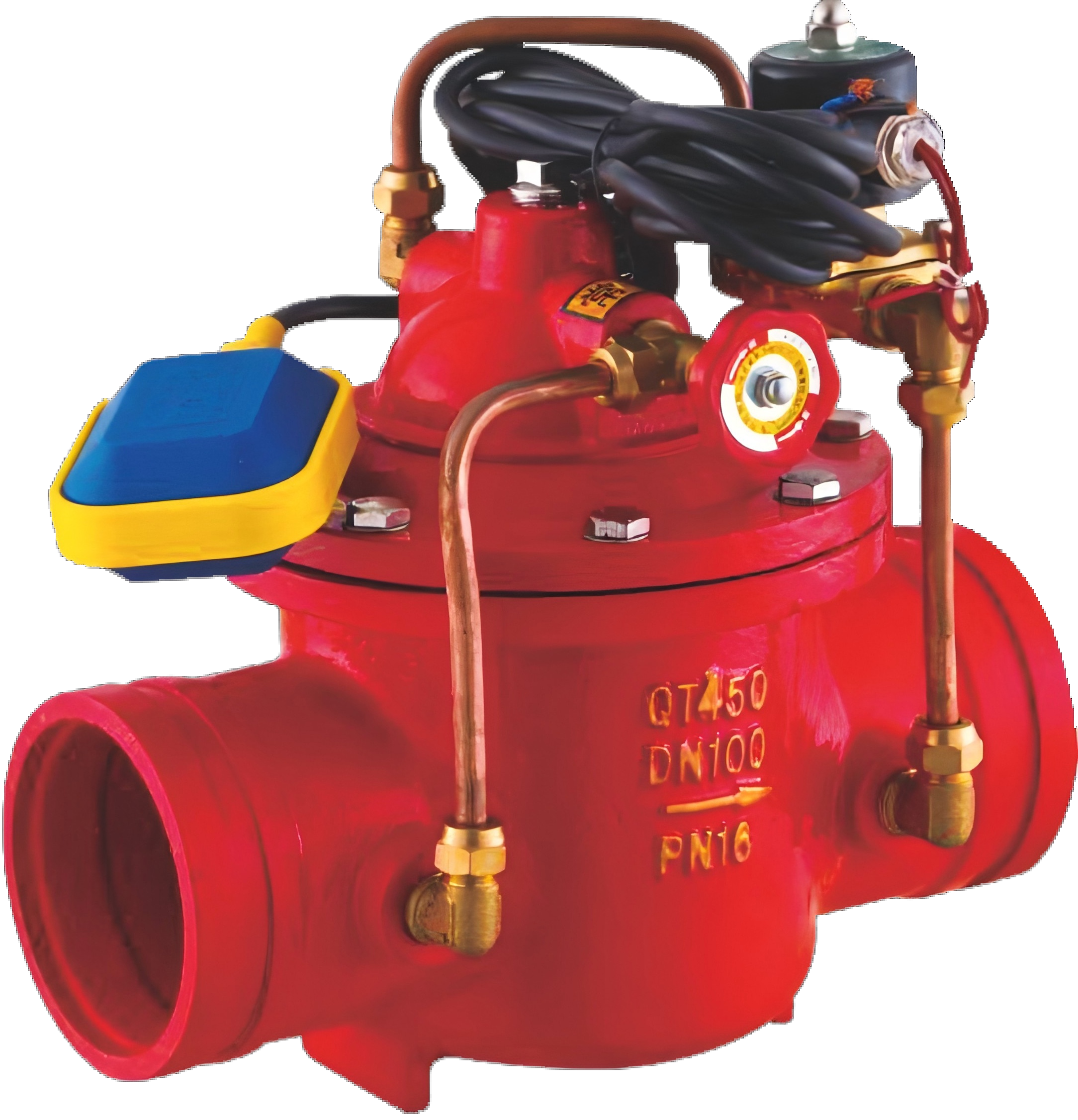
400X Diaphragm Type Flow Control Valve product image
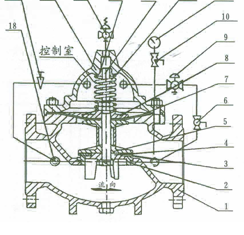
working principle
When the water pressure at the inlet end of the main valve enters the valve body and control chamber respectively (see structural diagram), and the ball valve 6 outside the main valve is closed at the same time, the main valve is in a fully closed state. When the ball valve 6 outside the main valve is fully opened, and the water pressure in the control room is fully arranged in the downstream low-pressure area, the main valve is in a fully open state. Adjust the opening of ball valve 6 outside the main valve to achieve balance between the water flow passing through needle valve 17 and ball valve 6. At this point, the main valve is in a floating state.
The flow control valve utilizes the pressure difference between the water flow entering the main valve control chamber through the conduit and needle valve 17, and is led to and controlled by the spring of the regulating conduit 9 to adjust the valve opening. The upper part of the main valve is adjusted to guide the regulating valve 15 to ensure the set opening of the main valve port, so that the flow in the pipeline does not exceed a certain set value. Even if the upstream pressure changes, it will not affect the downstream pressure. (This is the working principle of diaphragm type, and the same applies to piston type.)
structural form
The valve consists of a main valve, a pilot valve, a guide regulating valve, a needle valve, a ball valve, a micro filter, and a pressure gauge. Due to the fact that pilot valves, needle valves, and pressure gauges need to be connected to the main valve through conduits, they are collectively referred to as conduit control systems. Depending on the requirements of different pipe diameters, they can be divided into diaphragm and piston types.
Assembly drawing of 400X Diaphragm Type Flow Control Valve
Main Parts and Materials List
| Number | Part Name | Material | Number | Part Name | Material | |
| 1 | Valve Body | Cast Iron, Stainless Steel | 10 | Ball Valve | Copper | |
| 2 | Valve Seat | Copper, Stainless Steel | 11 | Pressure Gauge | ||
| 3 | Gasket | Reinforced Rubber | 12 | Compression Spring | Stainless Steel | |
| 4 | Gasket Pressure Plate | Copper, Stainless Steel | 13 | Valve Stem | Stainless Steel | |
| 5 | Valve Disc | Copper, Stainless Steel | 14 | Guide Sleeve | Stainless Steel | |
| 6 | Ball Valve | Copper | 15 | Pilot Regulating Valve | Stainless Steel | |
| 7 | Diaphragm | Reinforced Rubber | 16 | Valve Cover | Cast Iron, Stainless Steel | |
| 8 | Diaphragm Pressure Plate | Copper, Stainless Steel | 17 | Needle Valve | Copper | |
| 9 | Pilot Valve | Copper | 18 | Microfilter | Stainless Steel |
Main Technical Performance
| Nominal Pressure (PN) | 1.0MPa | 1.6MPa | 2.5MPa |
| Shell Test Pressure | 1.5MPa | 2.4MPa | 3.75MPa |
| Seal Test Pressure | 1.1MPa | 1.76MPa | 2.75MPa |
| Adjustable Range of Outlet Pressure | 0.09~0.8MPa | 0.10~1.2MPa | 0.15~1.6MPa |
| Pressure Characteristic △P2P1 | P2×8% | P2×10% | P2×12% |
| Flow Characteristic △P2G1 | P2×15% | P2×20% | P2×25% |
| Applicable Temperature | 0℃~80℃ | ||
| Applicable Medium | Water | ||
Main external dimensions
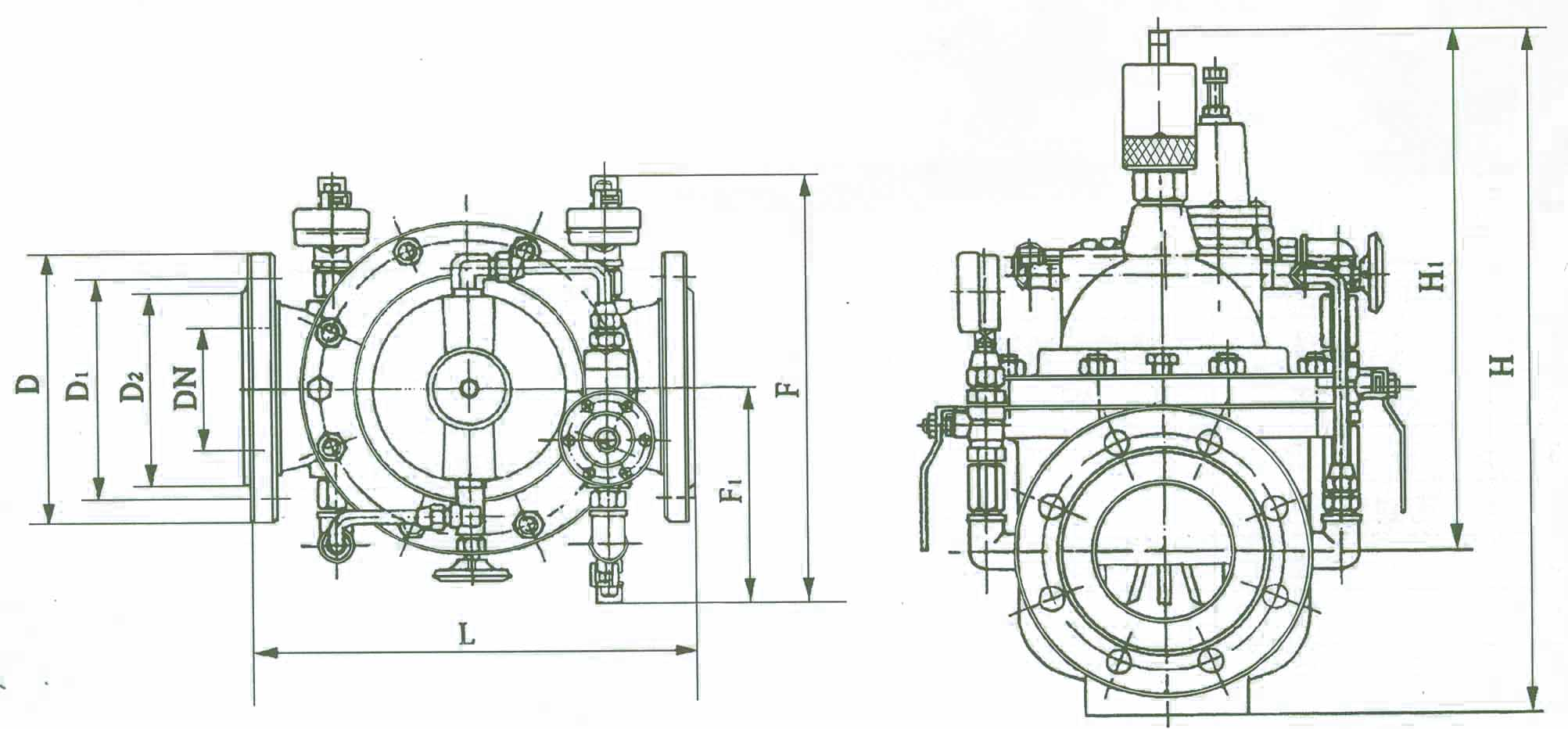
Outline dimension drawing of 400X Diaphragm Type Flow Control Valve
Installation dimension table for 400X Diaphragm Type Flow Control Valve
| DN | Dimension (mm) | ||||||||||||||||
| L | D | D1 | D2 | Z-фd | F1 | F | H1 | H | |||||||||
| PN10 | PN16 | PN25 | PN10 | PN16 | PN25 | PN10 | PN16 | PN25 | PN10 | PN16 | PN25 | ||||||
| 50 | 240 | 165 | 165 | 165 | 125 | 125 | 125 | 102 | 102 | 99 | 4-ф18 | 4-ф18 | 4-ф18 | 155 | 330 | 278 | 395 |
| 65 | 250 | 185 | 185 | 185 | 145 | 145 | 145 | 122 | 122 | 118 | 4-ф18 | 4-ф18 | 8-ф18 | 165 | 350 | 298 | 405 |
| 80 | 285 | 200 | 200 | 200 | 160 | 160 | 160 | 133 | 133 | 132 | 8-ф18 | 8-ф18 | 8-ф18 | 175 | 365 | 313 | 430 |
| 100 | 360 | 220 | 220 | 235 | 180 | 180 | 190 | 158 | 158 | 156 | 8-ф18 | 8-ф18 | 8-ф22 | 195 | 410 | 350 | 510 |
| 125 | 400 | 250 | 250 | 270 | 210 | 210 | 220 | 184 | 184 | 184 | 8-ф18 | 8-ф18 | 8-ф26 | 220 | 455 | 365 | 560 |
| 150 | 455 | 285 | 285 | 300 | 240 | 240 | 250 | 212 | 212 | 211 | 8-ф22 | 8-ф22 | 8-ф26 | 230 | 475 | 420 | 585 |
| 200 | 585 | 340 | 340 | 360 | 295 | 295 | 310 | 268 | 268 | 274 | 8-ф22 | 12-ф22 | 12-ф26 | 255 | 530 | 450 | 675 |
| 250 | 650 | 395 | 405 | 425 | 350 | 355 | 370 | 320 | 320 | 330 | 12-ф22 | 12-ф26 | 12-ф30 | 300 | 623 | 470 | 730 |
| 300 | 800 | 445 | 460 | 485 | 400 | 410 | 430 | 370 | 370 | 389 | 12-ф22 | 12-ф26 | 16-ф30 | 340 | 700 | 490 | 760 |
| 350 | 860 | 505 | 520 | 555 | 460 | 470 | 490 | 430 | 430 | 448 | 16-ф22 | 16-ф26 | 16-ф33 | 415 | 840 | 526 | 840 |
| 400 | 960 | 565 | 580 | 620 | 515 | 525 | 550 | 482 | 482 | 503 | 16-ф30 | 16-ф30 | 16-ф36 | 430 | 880 | 570 | 910 |
-
 900X Piston Emergency Shut-off Valve
Model:
900X-10/900X-16/900X-25/900X-10P/900X-16P/900X-25PSpecification:
DN350~DN800Pressure:
PN10~PN25Material:
Cast Iron, Stainless Steel -
 G106X groove hydraulic electric floating ball control valve
Model:
G106X-10/G106X-16/G106X-10Q/G106X-16Q/G106X-10P/G106X-16P/G106X-10T/G106X-16TSpecification:
DN50-DN600Pressure:
PN10~PN16Material:
Cast iron, ductile iron, stainless steel, copper -
 800X Differential Pressure (Bypass) Valve
Model:
800X-10P/800X-16P/800X-10T/800X-16TSpecification:
DN50~DN600Pressure:
PN10~PN16Material:
stainless steel, copper
Address:No. 1, Linxia Road, Sanqiao Industrial Zone, Oubei Sub-district, Yongjia County, Zhejiang Province| Switchboard:0577-67198981| mobile:+8613388552747| Email:sales@shanliuvalve.com|
COPYRIGHT © Zhejiang Shanliu Valve Technology Co., Ltd. Main Business: Water Valve Industrial valve|
浙ICP备2026020749号![]()