Your location:
 /
valves
/
check valve
/
Spherical Check Valve
/
HQ45X Micro-resistance Ball Check Valve
/
valves
/
check valve
/
Spherical Check Valve
/
HQ45X Micro-resistance Ball Check Valve

Mark Classification of Fluid products
- Phone:+86(577)67198981
- Fax:+86(577)67038872
- mobile:+8613388552747
- Sales Email 1:Karrie@shanliuvalve.com
- Sales Email 2:Yannie@shanliuvalve.com
- Sales Email 3:Merry@shanliuvalve.com
- Sales Email 4:Lucas@shanliuvalve.com
- Email:sales@shanliuvalve.com

HQ45X Micro-resistance Ball Check Valve
- Model:HQ45X-10Q/HQ45X-16Q/HQ45X-25Q/HQ45X-10/HQ45X-16/HQ45X-25
- Specification:DN300-DN1800
- Temperature:≤80℃
- Medium:Water、sewage
- Pressure:PN10,PN16,PN25
- Connection method:Flange
- Driving method:Automated
- Material:cast iron,ductile iron


Add QR code to serve you!
- Product Overview
- Performance Data
- Size Weight
HQ45X Micro-resistance Ball Check Valve Overview
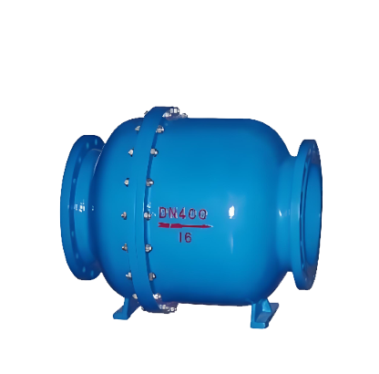
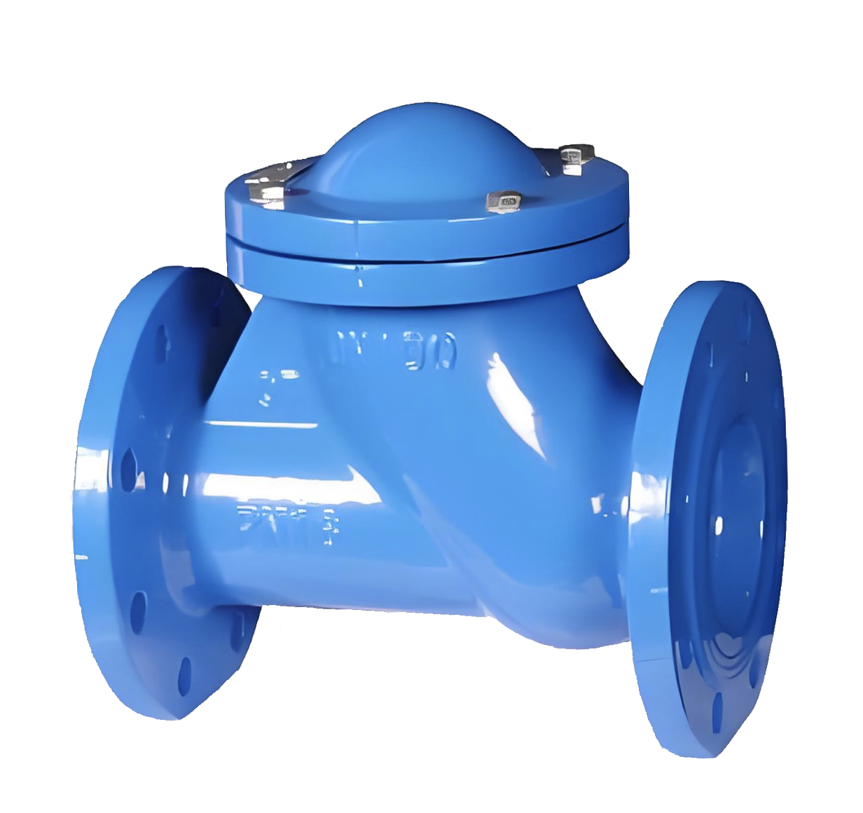
The HQ45X Micro-resistance ball check valve uses a rubber-coated ball as the valve disc, and its double-ball structure further optimizes the sealing and noise reduction effects. A dedicated slide rail is provided within the body, offering a stable path for the valve disc to roll and open/close. When the medium in the pipeline flows forward, the thrust of the medium pushes the double rubber-coated ball to roll along the slide rail within the body, thereby opening the valve and ensuring smooth passage of the medium.When the flow of the medium stops or a backflow tendency occurs, under the reverse pressure of the medium and with the assistance of related structures, the double balls will quickly reset and tightly fit against the valve seat, thus closing the valve and preventing backflow. Simultaneously, the double-ball structure can buffer the impact force during closure. Applications are concentrated in cold and hot water transmission networks, as well as industrial and domestic sewage networks. It is particularly suitable for installation at the pump outlet, preventing backflow to protect the pump and avoiding water hammer damage to equipment and pipelines.
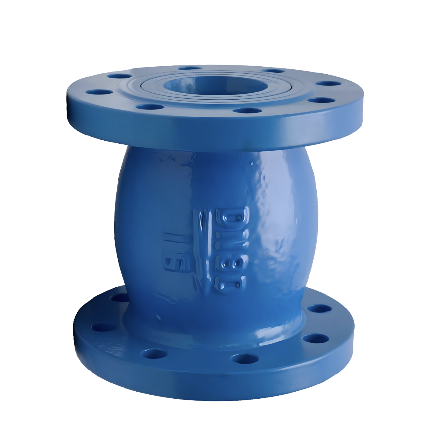
HQ45X Micro-resistance Ball Check Valve Product Image
HQ45X Micro-resistance Ball Check Valve features
1. Low flow resistance: Optimized flow channel design results in low fluid resistance and low energy consumption, suitable for high flow rate applications.
2. Reliable sealing: Excellent sealing performance between the ball and seat effectively prevents leakage and ensures system safety.
3. Silent closure: Reduces water hammer waves when closed, minimizing impact on pipes and equipment and reducing noise.
4. Flexible installation: Suitable for both horizontal and vertical installation, adaptable to various pipe layouts.

HQ45X Micro-resistance Ball Check Valve Structure Diagram
Parts Name Material List
| NO. | Name | Material |
| 3 | Body | Cast Iron |
| 2 | Ball | Rubber assembly |
| 1 | Seat | Cast steel、Cast Iron |
| Performance Specification | ||
| Nominal Pressure | 1.0/1.6/2.5 | MPa |
| Shell Test | 1.5/2.4/3.75 | |
| Seal Test | 1.1/1.76/2.75 | |
| Suitable Temp. | ≤80 | ℃ |
Dimensions Standard Requirements
1. The structural length of the valve shall conform to the standard GB/T12236.
2. The connecting flange shall conform to the standard GB/T17241.6
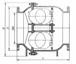
HQ45X Micro-resistance Ball Check Valve View Drawing
HQ45X Micro-resistance Ball Check Valve Dimensions Table
| Type | Size | DN | ||||||
| 300 | 350 | 400 | 450 | 500 | 600 | 700 | ||
| HQ45X-10 | L | 550 | 600 | 650 | 864 | 914 | 1067 | 1250 |
| D | 445 | 505 | 565 | 615 | 670 | 780 | 895 | |
| H | 580 | 650 | 715 | 810 | 1000 | 1120 | 1300 | |
| HQ45X-16 | L | 550 | 600 | 650 | 864 | 914 | 1067 | 1250 |
| D | 460 | 520 | 580 | 640 | 715 | 840 | 910 | |
| H | 580 | 650 | 715 | 810 | 1000 | 1120 | 1300 | |
| HQ45X-25Q | L | 550 | 600 | 650 | 864 | 914 | 1067 | 1250 |
| D | 485 | 555 | 620 | 670 | 730 | 845 | 960 | |
| H | 580 | 650 | 715 | 810 | 1000 | 1120 | 1300 | |
| Type | Size | DN | ||||||
| 800 | 900 | 1000 | 1200 | 1400 | 1600 | 1800 | ||
| HQ45X-10 | L | 1354 | 1420 | 1530 | 1645 | 1700 | 1800 | 2000 |
| D | 1015 | 1115 | 1230 | 1455 | 1675 | 1915 | 2115 | |
| H | 1450 | 1550 | 1750 | 1850 | 2180 | 2550 | 2750 | |
| HQ45X-16 | L | 1354 | 1420 | 1530 | 1645 | 1700 | 1800 | 2000 |
| D | 1025 | 1125 | 1255 | 1485 | 1685 | 1930 | 2130 | |
| H | 1450 | 1550 | 1750 | 1850 | 2180 | 2550 | 2750 | |
| HQ45X-25Q | 1354 | 1420 | 1530 | 1645 | 1700 | 1800 | 2000 | |
| D | 1085 | 1185 | 1320 | 1530 | 1755 | 1975 | 2195 | |
| H | 1450 | 1550 | 1750 | 1850 | 2180 | 2550 | 2750 | |
-
 HQ44X Vertical Ball Check Valve
Model:
HQ44X-10C/HQ44X-16C/HQ44X-25C/HQ44X-10Q/HQ44X-16Q/HQ44X-25QSpecification:
DN40-DN400Pressure:
PN10,PN16,PN25Material:
cast steel,ductile iron -
 HQ41X Ball Check Valve
Model:
HQ41X-10Q/HQ41X-16Q/HQ41X-10C/HQ41X-16C/HQ41X-10P/HQ41X-16PSpecification:
DN50-DN200Pressure:
PN10,PN16Material:
Ductile iron,cast iron

Complete Guide to Check Valve Selection and Installation: Detailed Explanation of Principles, Selection, and Key Construction Points Check valves, as crucial safety components in pipeline systems, are essential for preventing medium backflow and ensuring safe system operation. This article will provide you with a comprehensive guide to the selection and installation of check valves.
1. Operating Principle and Classification of Check Valves 1.1 What is a Check Valve?
Check valves, also known as one-way valves or non-return valves, belong to the category of automatic valves. Their working principle is to achieve opening and closing through the flow force of the medium itself. Their core function is to prevent the reverse flow of pipeline medium and ensure one-way flow.
1.2 Main application scenario: foot valve (a special type of check valve) at the water pump suction inlet
Various pipeline systems requiring unidirectional flow of medium
Industrial settings where accidents caused by medium backflow are to be prevented
II. Selection Criteria and Guidelines for Check Valves 2.1 Basic Selection Principles Medium Adaptability: Suitable for clean medium conditions, not recommended for pipelines containing solid particles or high viscosity media.
2.2 Selection of pipeline size (DN) based on pipeline size. Recommended valve types. Applicable pressure range: DN<50mm. Butterfly check valve, vertical lift check valve, diaphragm check valve. Low-pressure environment: 50mm
Advantages: Effectively eliminates the water hammer phenomenon
Limitations: Subject to temperature and pressure constraints, suitable for low-pressure and normal-temperature pipelines
Applicable scenario: Water supply pipelines prone to water hammer
Slow-closing check valve:
Slow-closing swing check valve
Slow-closing butterfly check valve
Applicable scenario: pipeline systems that require minimal or no water hammer impact when shut down
III. Installation specifications and construction requirements for check valves 3.1 Preparatory work before installation Appearance inspection:
Check the valve nameplate information to ensure compliance with the GB 12220 "General Valve Marking" standard
Check the integrity of the valve and confirm that it is undamaged
Pressure test requirements:
If the working pressure exceeds 1.0 MPa or the main pipe shut-off valve is involved, a pressure test must be conducted
Strength test: Nominal pressure × 1.5, duration ≥ 5 minutes, no leakage is considered as qualified
Tightness test: nominal pressure × 1.1, determine the duration according to GB 50243 standard
3.2 Installation location and direction: Strictly follow the design drawings to determine the location, height, and inlet and outlet directions
Flow direction indicator: Ensure that the flow direction of the medium is completely consistent with the direction indicated by the arrow on the valve body
Pipe support:
It is prohibited to let the check valve bear the weight of the pipeline
Large check valves must be equipped with independent support structures
Avoid direct impact of piping pressure on the valve
3.3 Lift check valves are required for specific types of installations:
Vertical flap type: It must be installed on a vertical pipeline
Horizontal flap type: It must be installed on a horizontal pipeline
Swing check valve:
Ensure that the valve disc's rotating shaft is in a horizontal position during installation
Special attention should be paid to the flow direction of the medium during inclined installation
IV. Common Installation Errors and Precautions 4.1 Example of Incorrect Installation: Installing a Vertical Lift Check Valve on a Horizontal Pipe
The valve flow direction is reversed
Large valves have no independent support
Pressure testing was not conducted according to specifications
4.2 The selection and installation location of check valves should be considered during the design phase of the professional advice system
Provide complete operating condition parameters to the supplier during procurement to obtain professional selection advice
For complex systems, it is recommended to consult a professional valve engineer
Conduct regular maintenance and inspection to ensure the check valve operates in normal condition
5. Maintenance points: Regularly check whether the valve can be opened and closed flexibly
Monitor for abnormal sounds, such as water hammer impact
Check the sealing performance to prevent internal leakage
Lubricate the moving parts to ensure normal operation
The correct selection and installation of check valves are crucial for ensuring the safe operation of pipeline systems. Following the selection guidelines and installation specifications provided in this article can prevent various accidents caused by medium backflow, extend the service life of valves, and reduce maintenance costs.
In practical applications, it is recommended to consider specific engineering requirements and medium characteristics, and if necessary, consult professional valve technicians to ensure the optimization of the selection and installation plan.
Address:No. 1, Linxia Road, Sanqiao Industrial Zone, Oubei Sub-district, Yongjia County, Zhejiang Province| Switchboard:0577-67198981| mobile:+8613388552747| Email:sales@shanliuvalve.com|
COPYRIGHT © Zhejiang Shanliu Valve Technology Co., Ltd. Main Business: Water Valve Industrial valve|
浙ICP备2026020749号![]()