Your location:
 /
valves
/
More water supply and drainage valves
/
Hydraulic Control Valve
/
700X Piston Pump Control Valve
/
valves
/
More water supply and drainage valves
/
Hydraulic Control Valve
/
700X Piston Pump Control Valve

Mark Classification of Fluid products
- Phone:+86(577)67198981
- Fax:+86(577)67038872
- mobile:+8613388552747
- Sales Email 1:Karrie@shanliuvalve.com
- Sales Email 2:Yannie@shanliuvalve.com
- Sales Email 3:Merry@shanliuvalve.com
- Sales Email 4:Lucas@shanliuvalve.com
- Email:sales@shanliuvalve.com


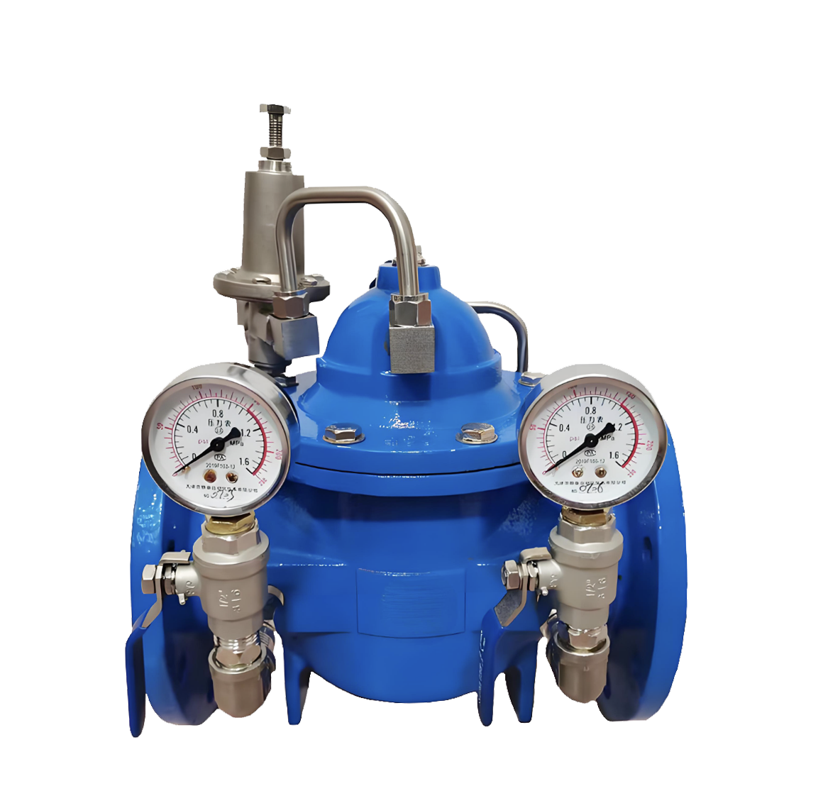
700X Piston Pump Control Valve
- Model:700X-10/700X-16/700X-25/700X-10P/700X-16P/700X-25P
- Specification:DN350~DN800
- Temperature:≤80℃
- Medium:Water, sewage, seawater, and media similar to water.
- Pressure:PN10~PN25
- Connection method:flange
- Driving method:Spring, automatic
- Material:Cast Iron,Ductile Iron,Carbon Steel,Stainless Steel


Add QR code to serve you!
- Product Overview
- Performance Data
- Size Weight
Product Introduction
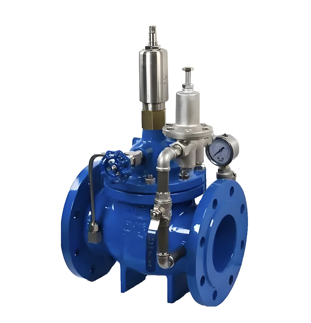
This product is designed and manufactured by our factory's engineers with reference to advanced domestic and foreign similar products. The valve body features a streamlined design, ensuring low fluid resistance, large flow rate, and excellent sealing performance. Equipped with a solenoid valve-guided pipeline control system, it operates hydraulically and is commonly used for automatic control in water supply, drainage, and industrial systems, enabling remote operation of valve opening and closing. It can be additionally fitted with a speed control device. This product replaces large electric devices for gate valves and butterfly valves, offering advantages such as small size, light weight, easy maintenance, convenient operation, safety, and reliability. Welcome to purchase!
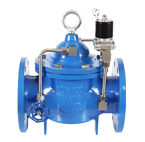
Product diagram of 700X Piston Pump Control Valve
Working Principle
When the water pump starts operating, the water flow at the inlet end enters the valve cover control chamber through needle valve 3 and check valve 1, and then is discharged to the outlet through check valve 2, solenoid pilot valve 7, and ball valve 8. When the valve disc opens to 10%, it touches the electrical control switch, at which point the solenoid pilot valve is energized and remains in a normally closed state. Due to the small opening of needle valve 3 (usually 1/4 turn open) and the smaller diameter of the inlet pipe compared to the outlet pipe, the discharge speed in the control chamber is higher than the water replenishment speed. As a result, the pressure in the control chamber decreases, and the inlet pressure lifts the main valve disc to supply a large amount of water downstream. When water supply needs to be stopped, before the water pump shuts down, the inlet pressure first closes 90% of the main valve. At this time, the solenoid pilot valve 7 is in a normally open state due to power failure. For the remaining 10%, the pressure in the upper water chamber gradually increases through the action of solenoid pilot valve 7 and check valves 1 and 2, eventually closing the main valve disc tightly. This can completely prevent water hammer, protect the water pump motor, and also achieve slow closing and noise reduction.
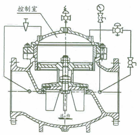
Structural diagram of 700X Piston Pump Control Valve
Main Components and Materials
| Serial Number | Part Name | Material | Serial Number | Part Name | Material | ||
| Diaphragm Type | Piston Type | Diaphragm Type | Piston Type | ||||
| 1 | 1 | Valve Cover | Cast IronDuctile IronCarbon SteelStainless Steel | 4 | O-Ring | Nitrile Rubber | |
| 2 | Compression Spring | Silicon-Manganese Steel | 5 | 5 | Valve Stem | Stainless Steel | |
| 2 | Cylinder Liner | Stainless Steel | 6 | 6 | Valve Disc | Ductile IronBronze | |
| 3 | Diaphragm Pressure Plate | Nitrile Rubber | 7 | 7 | Gasket | Nitrile Rubber | |
| 3 | Piston | Ductile IronBronze | 8 | 8 | Valve Body | Cast IronDuctile IronCarbon SteelStainless Steel | |
| 4 | Diaphragm | Nitrile Rubber | 9 | 9 | Gasket Pressure Plate | Bronze | |
Main Technical Performance
| Nominal Pressure PN | 1.0MPa | 1.6MPa | 2.5MPa |
| Shell Test Pressure | 1.5MPa | 2.4MPa | 3.75MPa |
| Seal Test Pressure | 1.1MPa | 1.76MPa | 2.75MPa |
| Applicable Temperature | 0℃~80℃ | ||
| Applicable Medium | Water | ||
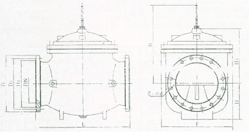
700X Piston Pump Control Valve Outline Dimension Drawing
700X Piston Pump Control Valve Outline Dimension Table
| Nominal Diameter | Dimensions(mm) | ||||||||||||
| L | D | D1 | D2 | Z-фd | H | H1 | B | F | |||||
| PN10 | PN16 | PN10 | PN16 | PN10 | PN16 | PN10 | PN16 | ||||||
| 350 | 860 | 505 | 520 | 460 | 470 | 430 | 438 | 16-ф22 | 16-ф26 | 340 | 495 | 650 | 640 |
| 400 | 960 | 565 | 580 | 515 | 525 | 482 | 490 | 16-ф26 | 16-ф30 | 380 | 550 | 730 | 715 |
| 450 | 1075 | 615 | 640 | 565 | 585 | 532 | 550 | 20-ф26 | 20-ф30 | 420 | 610 | 800 | 780 |
| 500 | 1075 | 670 | 715 | 620 | 650 | 585 | 610 | 20-ф26 | 20-ф33 | 470 | 665 | 880 | 830 |
| 600 | 1230 | 780 | 840 | 725 | 770 | 685 | 725 | 20-ф30 | 20-ф36 | 545 | 725 | 980 | 880 |
| 700 | 1650 | 895 | 910 | 840 | 840 | 800 | 795 | 24-ф30 | 24-ф36 | 595 | 865 | 1150 | 980 |
| 800 | 1750 | 1015 | 1025 | 950 | 950 | 905 | 900 | 24-ф33 | 24-ф39 | 665 | 975 | 1300 | 1050 |
-
 400X Diaphragm Type Flow Control Valve
Model:
400X-10/400X-16/400X-25/400X-10P/400X-16P/400X-25PSpecification:
DN50~DN400Pressure:
PN10~PN25Material:
Cast iron, stainless steel, -
 200X Piston Type Pressure Reducing Valve
Model:
200X-10/200X-16/200X-25/200X-10P/200X-16P/200X-25PSpecification:
DN350~DN800Pressure:
PN10~PN25Material:
Cast Iron, Cast Steel, Stainless Steel,Copper -
 200X Diaphragm Pressure Reducing Valve
Model:
200X-10/200X-16/200X-25/200X-10Q/200X-16Q/200X-25Q/200X-10P/200X-16P/200X-25P/200X-10T/200X-16T/200X-25TSpecification:
DN50~DN400Pressure:
PN10~PN25Material:
Cast iron, ductile iron, stainless steel, copper
Address:No. 1, Linxia Road, Sanqiao Industrial Zone, Oubei Sub-district, Yongjia County, Zhejiang Province| Switchboard:0577-67198981| mobile:+8613388552747| Email:sales@shanliuvalve.com|
COPYRIGHT © Zhejiang Shanliu Valve Technology Co., Ltd. Main Business: Water Valve Industrial valve|
浙ICP备2026020749号![]()