Your location:
 /
valves
/
Pressure Reducing Valve
/
Steam Pressure Reducing Valve
/
ZZYP Self-Operated Pressure Reducing Valve
/
valves
/
Pressure Reducing Valve
/
Steam Pressure Reducing Valve
/
ZZYP Self-Operated Pressure Reducing Valve

Mark Classification of Fluid products
- Phone:+86(577)67198981
- Fax:+86(577)67038872
- mobile:+8613388552747
- Sales Email 1:Karrie@shanliuvalve.com
- Sales Email 2:Yannie@shanliuvalve.com
- Sales Email 3:Merry@shanliuvalve.com
- Sales Email 4:Lucas@shanliuvalve.com
- Email:sales@shanliuvalve.com

ZZYP Self-Operated Pressure Reducing Valve
- Model:ZZYP - 16C/ZZYP - 16P/ZZYP - 40P/ZZYP - 64P
- Specification:DN20-DN300
- Temperature:≤80℃
- Medium:Gaseous, Liquid and Steam
- Pressure:PN16,PN40,PN64
- Connection method:Flange
- Driving method:Automated
- Material:Stainless steel,carbon steel


Add QR code to serve you!
- Product Overview
- Performance Data
- Size Weight
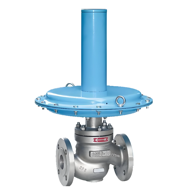
ZZYP Self-Operated Pressure Reducing Valve Overview
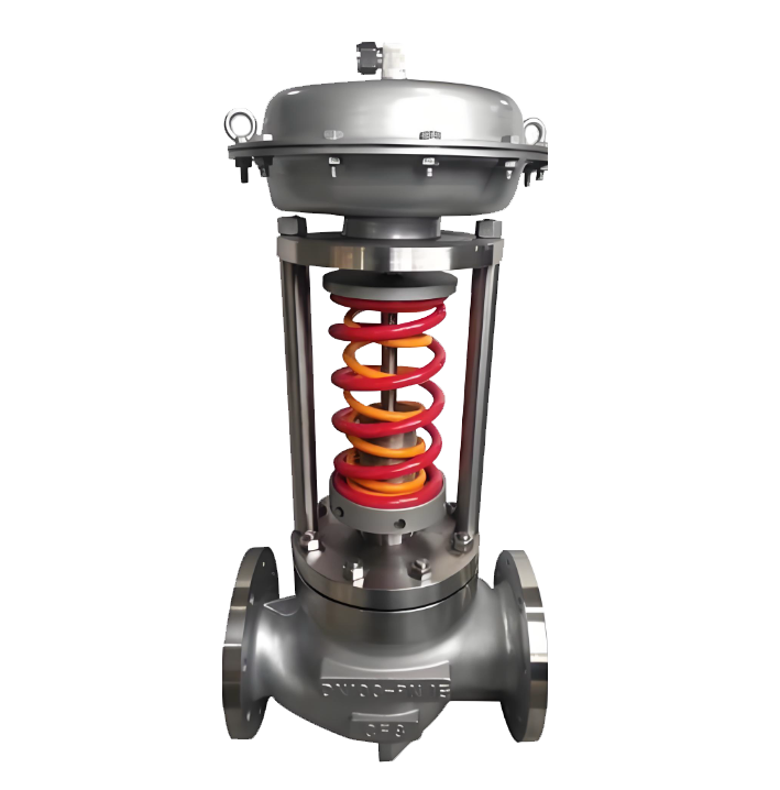
The ZZYP self-operated pressure reducing valve is an automatic pressure regulating device driven by the medium's own energy. Adopting the direct-acting pressure sensing and control principle, it can accurately regulate and stably output the pipeline system pressure without external power supply or air source. The valve senses downstream pressure changes through built-in pressure sensing elements (such as diaphragms and bellows) and drives the valve core to automatically adjust the opening degree, thereby stably reducing the high and unstable pressure at the inlet to the set outlet pressure value. Its design emphasizes energy efficiency and reliability, and it is widely used in pressure control occasions without external power or with high explosion-proof requirements, such as steam heating, compressed air, gas supply, and industrial fluids. The valve adopts a cast steel, stainless steel or copper alloy valve body with a compact and robust structure, supporting flange and thread connection methods. It is a key equipment for realizing pressure zoning control of process systems, pressure stabilization at equipment inlets, and safe and energy-saving operation.
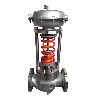
ZZYP Self-Operated Pressure Reducing Valve Product Image
ZZYP Self-Operated Pressure Reducing Valve Features
1. Self-Operated Drive for Energy Saving and Reliability
It fully utilizes the pipeline medium's own pressure as the driving energy, realizing automatic pressure stabilization without relying on external power supply, air source or complex control systems. This design not only reduces energy consumption and operating costs but also avoids control failure caused by external power faults, ensuring high system reliability.
2. Direct-Acting Sensitive Regulation
Equipped with a force balance system composed of high-sensitivity pressure sensing elements (diaphragm/bellows) and precision springs, it responds quickly and directly to downstream pressure changes. The regulating mechanism has no intermediate transmission links, featuring timely dynamic response and stable pressure control with an accuracy of ±5%~10% of the set value.
3. Compact Structure and Strong Adaptability
Adopting an integrated valve body design, it is small in size and flexible in installation, supporting horizontal or vertical mounting. It is widely applicable to various media such as steam, compressed air, nitrogen, liquefied gas and oil products, with a wide operating temperature range (-20℃~350℃) and pressure resistance grade up to PN16~PN40.
4. Versatile Control with Flexible Configuration
By replacing the actuator type or adjusting the pressure guiding configuration, it can achieve multiple functions including downstream pressure regulation (pressure reducing and stabilizing), upstream pressure regulation (pressure relief and holding) and differential pressure control, meeting different pressure control needs of process systems.
5. Easy Maintenance and Long-Term Stability
The control mechanism adopts a modular design, and main wearing parts (such as diaphragms and sealing rings) can be quickly replaced without disassembling the valve body during maintenance. The overall structure is robust, and key components are treated for corrosion and wear resistance, making it suitable for continuous operation with long service life and low maintenance costs.
ZZYP Self-Operated Pressure Reducing Valve Structure Diagram
Parts Name Material List
| NO. | Name | Material |
| 1 | body | ZG230-450、ZG1Cr18Ni9Ti 、ZGCr18Ni12Mo2Ti |
| 2 | stem | 1Cr18Ni9Ti 、Cr18Ni12Mo2T |
| 3 | diaphragm cover | A3、A3 Steel Coated with PTFE、stainless steel |
| 4 | packing | EPDM、Fluoro Rubber、Oil-Resistant Rubber |
| 5 | Valve Core | 1Cr18Ni9Ti 、Cr18Ni12Mo2Ti |
| 6 | seat | 1Cr18Ni9Ti 、Cr18Ni12Mo2Ti |
| Performance Specification | ||
| Nominal Pressure | 1.6/4/6.4 | MPa |
| Shell Test | 2.4/6/9.6 | |
| Seal Test | 1.76/4.4/7.04 | |
| Suitable Temp. | ≤80 | ℃ |
Dimensions Standard Requirements
1. The structural length of the valve shall conform to the standard GB/T12250.
2. The connecting flange shall conform to the standard GB/T 79.

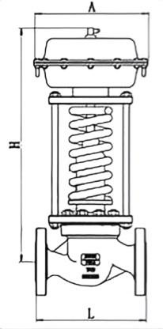
ZZYP Self-Operated Pressure Reducing Valve View Drawing
ZZYP Self-Operated Pressure Reducing Valve Dimension Table
| 公称通径(DN) | 20 | 25 | 32 | 40 | 50 | 65 | 80 | 100 | 125 | 150 | 200 | ||
| L | PN16、40 | 150 | 160 | 180 | 200 | 230 | 290 | 310 | 350 | 400 | 480 | 600 | |
| PN64 | 230 | 230 | 260 | 260 | 300 | 340 | 380 | 430 | 500 | 550 | 650 | ||
| B | 233 | 332 | 373 | 522 | 673 | 980 | 1200 | ||||||
| H | Pressure regulating range | 15~140 | 475 | 520 | 540 | 710 | 780 | 840 | 880 | 915 | |||
| 120~300 | 455 | 500 | 520 | 690 | 760 | 800 | 870 | 880 | |||||
| 280~500 | 450 | 490 | 510 | 680 | 750 | 790 | 860 | 870 | |||||
| 480~1000 | 445 | 480 | 670 | 740 | 780 | 850 | 860 | ||||||
| 600~1500 | 445 | 570 | 600 | 820 | 890 | 950 | 950 | 1000 | |||||
| 1000~2500 | 445 | 570 600 820 890 950 950 1000 | |||||||||||
| A | Pressure regulating range | 15~140 | 中282 | 中308 | |||||||||
| 120~300 | 中232 | ||||||||||||
| 280~1000 | 中196 | 中196 | 中282 | ||||||||||
| 600~2500 | 中85 中96 | ||||||||||||
-
 Y43H Steam Pressure Reducing Valve (Spirax Sarco Type)
Model:
Y43H-DP27/Y43H-DPE/Y43H-DP27YSpecification:
DN15-DN50Pressure:
PN10,PN21,PN25Material:
Cast Iron, Carbon Steel, Stainless Steel -
 ZZVP Self-Operated Micro-Pressure Regulating Valve
Model:
ZZVP - 16C/ZZVP - 16C/ZZVP - 10B/ZZVP - 16P/ZZVP - 16P/ZZVP - 10B/PSpecification:
DN20-DN150Pressure:
PN10,PN16Material:
Stainless steel,carbon steel -
 ZYS Self-Operated Pressure Reducing Valve Assembly
Model:
zysSpecification:
DN20-DN300Pressure:
PN16,PN40,PN64Material:
Cast Steel、Stainless Steel

Is the noise from the pressure reducing valve disturbing? Understand the 3 fundamental reasons and solutions in one article
The harsh noise generated by pressure reducing valves during operation is not only an environmental pollution problem, but also a precursor to equipment failure. This article will delve into the three fundamental causes of noise generated by pressure reducing valves - mechanical vibration noise, fluid dynamics noise, and aerodynamic noise, and provide professional solutions.
1、 Mechanical vibration noise: a test of design and process
Mechanical vibration noise is the most common type of noise in pressure reducing valves, mainly divided into two forms:
1. Low frequency vibration noise
Causes:
Medium jet and pressure pulsation
The outlet flow rate of the valve is too fast
Unreasonable pipeline layout
Insufficient rigidity of moving parts inside the valve
2. High frequency vibration noise (resonance phenomenon)
Causes:
The natural frequency of the valve coincides with the excitation frequency of the medium
Easy to occur within a specific decompression range
Sensitive to changes in working conditions, with significant noise fluctuations
Solution:
Optimize the clearance design between the liner and valve stem
Improve machining accuracy
Adjust the natural frequency of the valve
Enhance the rigidity of active components
Select appropriate damping materials
2、 Fluid Dynamics Noise: Challenges in Fluid Control
The turbulence and eddies generated when the fluid passes through the pressure reducing valve can cause significant noise problems.
1. Turbulent noise
Features: Low frequency, low noise level
Cause: Interaction between turbulent fluid and the inner surface of valves/pipelines
Impact: Usually does not constitute a serious noise problem
2. Cavitation noise (the most harmful)
Production mechanism:
During the depressurization process, the fluid flow velocity reaches the critical value
The liquid begins to vaporize, producing bubbles
Bubble explosion under pressure generates shock waves
Local instantaneous pressure can reach 196 MPa
Key data:
Initial value of Δ p: the critical pressure reduction value at which liquid begins to cavitation
Exceeding this value leads to a sharp increase in noise
Preventive measures:
Control the actual pressure reduction value below the critical value
Optimize the design of valve disc fluid direction
Adopting a multi-stage decompression structure
Choose anti cavitation materials
3、 Aerodynamic noise: characteristics of compressible fluids
When compressible fluids such as steam pass through pressure reducing areas, unique noise issues arise:
Production principle:
Conversion of fluid mechanical energy into sound energy
Interaction between high-speed airflow and valve structure
Sudden pressure changes cause gas expansion and sound emission
Control method:
Optimize the design of pressure reducing flow channels
Using mufflers or diffusers
Control the outlet flow rate
Reasonably set back pressure
Comprehensive solutions and selection suggestions
Preventive measures during the design phase
Parameter optimization: Accurately calculate operating parameters to ensure that the pressure reduction value is within the design range
Structural design: Adopting streamlined flow channels to reduce turbulence generation
Material selection: Select special alloys with high rigidity and cavitation resistance
Frequency analysis: avoid the natural frequency of the valve coinciding with the excitation frequency
Key points for installation and maintenance
Correct installation: Ensure the length of the front and rear straight pipe sections to avoid sharp bends
Regular testing: Establish a noise monitoring mechanism to detect problems early on
Timely maintenance: replace worn parts and maintain the best condition of the valve
Brand selection recommendation
High pressure differential operating condition: choose multi-stage pressure reducing valve
Liquid medium: focus on anti cavitation design
Gas/Steam: Focus on Aerodynamic Optimization
Sensitive environment: Choose a low-noise dedicated model
Professional Technical Summary
The essence of the noise problem of pressure reducing valves is the process of energy conversion and release. Fundamentally, all noise issues are closely related to the rationality of valve design, manufacturing process accuracy, and compatibility with operating conditions. Through scientific selection, correct installation, and standardized maintenance, it is entirely possible to control the noise of the pressure reducing valve within an acceptable range.
Immediate action suggestion: If you are troubled by pressure reducing valve noise, it is recommended to first record the noise characteristics (frequency, time period, change pattern), check whether the operating parameters deviate from the design values, and promptly contact professional technicians for diagnosis and treatment.
Keywords of this article: pressure reducing valve noise, mechanical vibration noise, cavitation noise, fluid dynamics noise, pressure reducing valve failure, valve noise reduction, industrial noise control, equipment maintenance
Extended reading: For more professional knowledge about industrial valve selection and maintenance, please follow our technical column to obtain the latest solutions and industry practice cases.
Address:No. 1, Linxia Road, Sanqiao Industrial Zone, Oubei Sub-district, Yongjia County, Zhejiang Province| Switchboard:0577-67198981| mobile:+8613388552747| Email:sales@shanliuvalve.com|
COPYRIGHT © Zhejiang Shanliu Valve Technology Co., Ltd. Main Business: Water Valve Industrial valve|
浙ICP备2026020749号![]()