Your location:
 /
valves
/
More water supply and drainage valves
/
Hydraulic Control Valve
/
400X Piston Type Flow Control Valve
/
valves
/
More water supply and drainage valves
/
Hydraulic Control Valve
/
400X Piston Type Flow Control Valve

Mark Classification of Fluid products
- Phone:+86(577)67198981
- Fax:+86(577)67038872
- mobile:+8613388552747
- Sales Email 1:Karrie@shanliuvalve.com
- Sales Email 2:Yannie@shanliuvalve.com
- Sales Email 3:Merry@shanliuvalve.com
- Sales Email 4:Lucas@shanliuvalve.com
- Email:sales@shanliuvalve.com


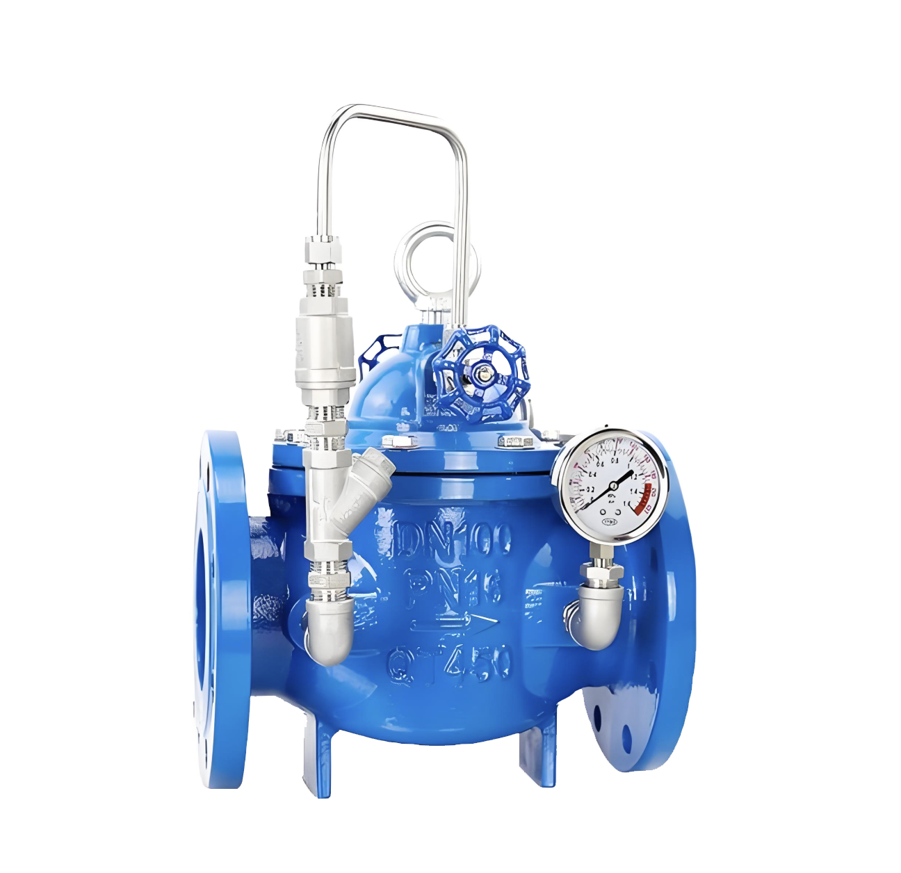
400X Piston Type Flow Control Valve
- Model:400X-10/400X-16/400X-25/400X-10P/400X-16P/400X-25P
- Specification:DN350~DN800
- Temperature:≤80℃
- Medium:Water and water-like media
- Pressure:PN10~DN25
- Connection method:flange
- Driving method:Spring, automatic
- Material:Cast Iron,Stainless Steel


Add QR code to serve you!
- Product Overview
- Performance Data
- Size Weight
Product Introduction
This product, developed by our engineering and technical personnel through the introduction of new technologies as well as improvements in manufacturing processes and structures, has reached the advanced level of international similar products. The valve body adopts a full-channel streamlined design, featuring low fluid resistance and large flow rate. It uses hydraulic operation in terms of transmission mode, that is, the water pressure in the pipeline is utilized to automatically control the vertical movement of the main valve disc and adjust the opening of the main valve port. The main valve is installed in the pipeline for controlling flow in water supply and distribution pipelines. By presetting and adjusting the pilot regulating valve and a fixed flow rate of the pilot valve on the upper part of the valve, the flow rate through the main valve can be kept constant without being affected even if the pressure upstream of the main valve changes. In a word, this product is an ideal choice for domestic water supply, fire protection systems and industrial water supply systems.
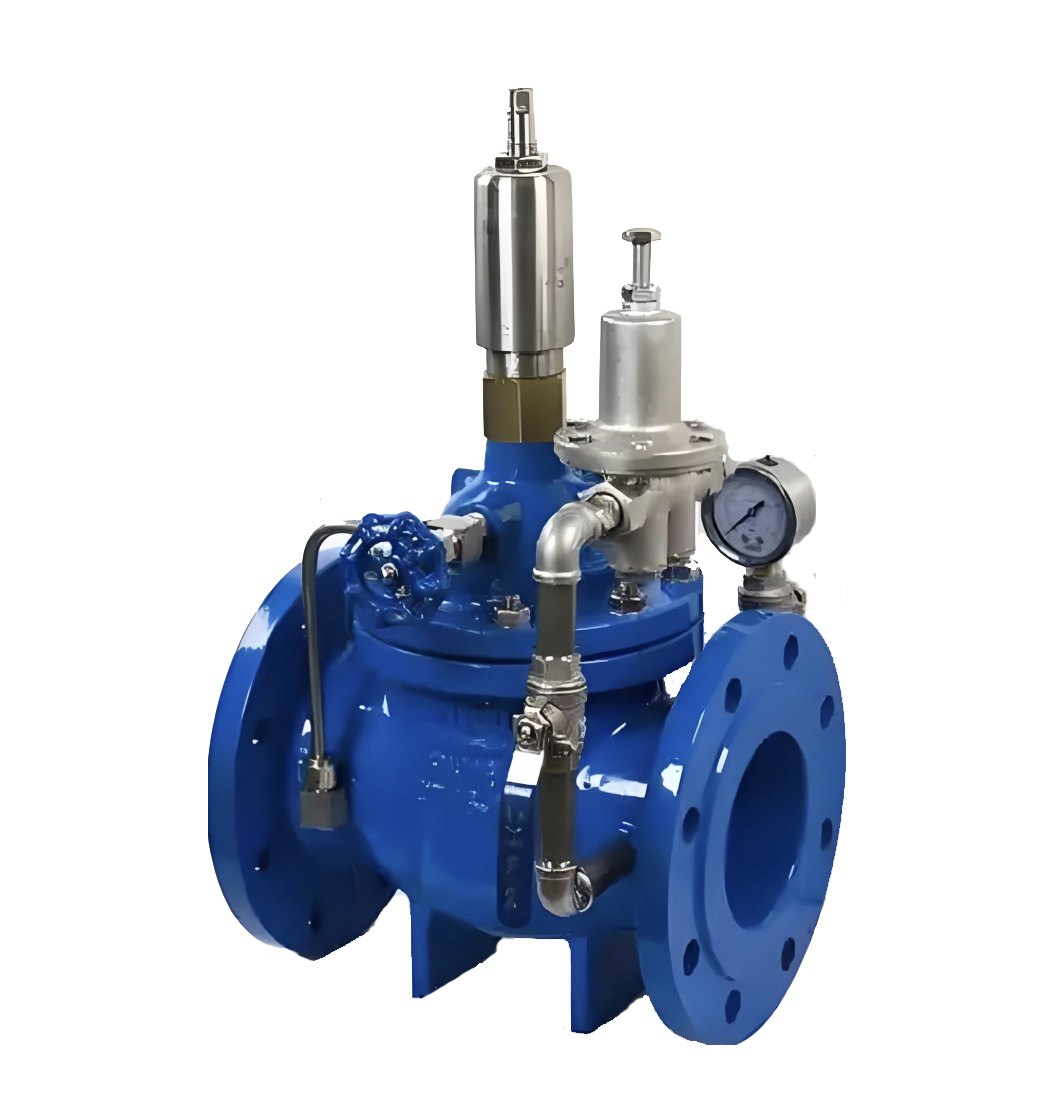
400X Piston Type Flow Control Valve Product Diagram
Working Principle
When the water pressure at the inlet of the main valve enters the valve body and the control chamber (see the structure diagram) respectively, and the ball valve 6 outside the main valve is closed at the same time, the main valve is in a fully closed state. When the ball valve 6 outside the main valve is fully opened, all the water pressure in the control chamber is discharged to the low-pressure area downstream, and the main valve is in a fully open state. Adjust the opening degree of the ball valve 6 outside the main valve to balance the water flow through the needle valve 17 and the ball valve 6, and the main valve is in a floating state.The flow control valve uses the pressure difference of water flow entering the main valve control chamber through the conduit and the needle valve 17, leads the pipe to and controls the valve opening degree by means of the spring of the adjusting conduit 9, and adjusts the pilot regulating valve 15 on the upper part of the main valve to ensure the set opening degree of the main valve port, so that the flow in the pipeline does not exceed a certain set value. Even if the upstream pressure changes, it will not affect the downstream pressure. (This is the working principle of the diaphragm type, and the same applies to the piston type.)
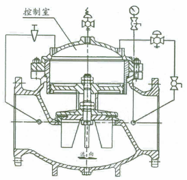
Structural Diagram of 400X Piston Type Flow Control Valve
Main Parts and Materials
| Number | Part Name | Material | Number | Part Name | Material | |
| 1 | Valve Body | Cast Iron, Stainless Steel | 10 | Ball Valve | Copper | |
| 2 | Valve Seat | Copper, Stainless Steel | 11 | Pressure Gauge | ||
| 3 | Gasket | Reinforced Rubber | 12 | Compression Spring | Stainless Steel | |
| 4 | Gasket Pressure Plate | Copper, Stainless Steel | 13 | Valve Stem | Stainless Steel | |
| 5 | Valve Disc | Copper, Stainless Steel | 14 | Guide Sleeve | Stainless Steel | |
| 6 | Ball Valve | Copper | 15 | Pilot Regulating Valve | Stainless Steel | |
| 7 | Diaphragm | Reinforced Rubber | 16 | Valve Cover | Cast Iron, Stainless Steel | |
| 8 | Diaphragm Pressure Plate | Copper, Stainless Steel | 17 | Needle Valve | Copper | |
| 9 | Pilot Valve | Copper | 18 | Microfilter | Stainless Steel |
Main Technical Performance
| Nominal Pressure (PN) | 1.0MPa | 1.6MPa | 2.5MPa |
| Shell Test Pressure | 1.5MPa | 2.4MPa | 3.75MPa |
| Seal Test Pressure | 1.1MPa | 1.76MPa | 2.75MPa |
| Adjustable Range of Outlet Pressure | 0.09~0.8MPa | 0.10~1.2MPa | 0.15~1.6MPa |
| Pressure Characteristic △P2P1 | P2×8% | P2×10% | P2×12% |
| Flow Characteristic △P2G1 | P2×15% | P2×20% | P2×25% |
| Applicable Temperature | 0℃~80℃ | ||
| Applicable Medium | Water | ||
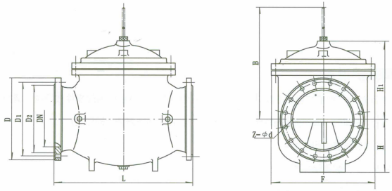
Outline Dimension Drawing of 400X Piston Type Flow Control Valve
Outline Dimension Table of 400X Piston Type Flow Control Valve
| DN | Dimension(mm) | ||||||||||||
| L | D | D1 | D2 | Z-фd | H | H1 | B | F | |||||
| PN10 | PN16 | PN10 | PN16 | PN10 | PN16 | PN10 | PN16 | ||||||
| 350 | 860 | 505 | 520 | 460 | 470 | 430 | 438 | 16-ф22 | 16-ф26 | 340 | 495 | 650 | 640 |
| 400 | 960 | 565 | 580 | 515 | 525 | 482 | 490 | 16-ф26 | 16-ф30 | 380 | 550 | 730 | 715 |
| 450 | 1075 | 615 | 640 | 565 | 585 | 532 | 550 | 20-ф26 | 20-ф30 | 420 | 610 | 800 | 780 |
| 500 | 1075 | 670 | 715 | 620 | 650 | 585 | 610 | 20-ф26 | 20-ф33 | 470 | 665 | 880 | 830 |
| 600 | 1230 | 780 | 840 | 725 | 770 | 685 | 725 | 20-ф30 | 20-ф36 | 545 | 725 | 980 | 880 |
| 700 | 1650 | 895 | 910 | 840 | 840 | 800 | 795 | 24-ф30 | 24-ф36 | 595 | 865 | 1150 | 980 |
| 800 | 1750 | 1015 | 1025 | 950 | 950 | 905 | 900 | 24-ф33 | 24-ф39 | 665 | 975 | 1300 | 1050 |
-
 700X Piston Pump Control Valve
Model:
700X-10/700X-16/700X-25/700X-10P/700X-16P/700X-25PSpecification:
DN350~DN800Pressure:
PN10~PN25Material:
Cast Iron,Ductile Iron,Carbon Steel,Stainless Steel -
 700X Diaphragm Pump Control Valve
Model:
700X-10/700X-16/700X-25/700X-10P/700X-16P/700X-25PSpecification:
DN50~DN400Pressure:
PN10~PN25Material:
Cast Iron Ductile Iron Carbon Steel Stainless Steel -
 300X Diaphragm type Slow closing Check Valve
Model:
300X-10/300X-16/300X-25/300X-10P/300X-16P/300X-25PSpecification:
DN50~DN400Pressure:
PN10~PN25Material:
Cast iron, stainless steel
Address:No. 1, Linxia Road, Sanqiao Industrial Zone, Oubei Sub-district, Yongjia County, Zhejiang Province| Switchboard:0577-67198981| mobile:+8613388552747| Email:sales@shanliuvalve.com|
COPYRIGHT © Zhejiang Shanliu Valve Technology Co., Ltd. Main Business: Water Valve Industrial valve|
浙ICP备2026020749号![]()