Your location:
 /
valves
/
check valve
/
Lift Check Valve
/
H61Y Forged Steel Y-Type Check Valve
/
valves
/
check valve
/
Lift Check Valve
/
H61Y Forged Steel Y-Type Check Valve

Mark Classification of Fluid products
- Phone:+86(577)67198981
- Fax:+86(577)67038872
- mobile:+8613388552747
- Sales Email 1:Karrie@shanliuvalve.com
- Sales Email 2:Yannie@shanliuvalve.com
- Sales Email 3:Merry@shanliuvalve.com
- Sales Email 4:Lucas@shanliuvalve.com
- Email:sales@shanliuvalve.com

H61Y Forged Steel Y-Type Check Valve
- Model: H61Y
- Specification:DN10-50
- Temperature:≤ 550 ℃
- Medium:Water, Oil , Steam
- Pressure:PN20-PN150
- Connection method:NPT
- Driving method:automated
- Material:forged steel,forged stainless steel


Add QR code to serve you!
- Product Overview
- Performance Data
- Size Weight
H61Y Forged Steel Y-Type Check Valve Overview
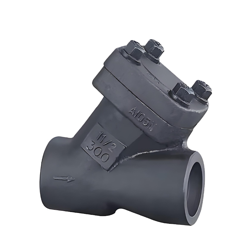
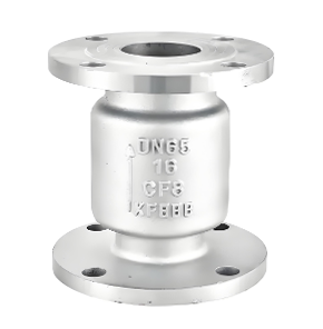
The H61Y Forged Steel Y-Type Check Valve is a specially designed check valve featuring a forged steel body with internal thread or butt-weld connections, characterized by a Y-shaped flow path and an internal lift-type disc structure. The valve body is forged from materials such as A105, offering excellent mechanical properties and pressure-bearing capacity. The sealing surfaces of the disc and seat typically employ metal hard seals overlay-welded with hard alloys.The valve operates by lifting the disc open under forward medium pressure and achieving rapid closure under the disc's own weight with spring assistance. The Y-shaped design ensures a smooth flow path transition, significantly reducing flow resistance and pressure loss.Specifically engineered for small-diameter pipelines with high pressure, high flow velocity, and stringent pressure drop requirements, this valve is widely used in petrochemical plants, power stations, high-pressure boiler feedwater systems, and instrument measurement pipelines. It serves as a high-performance, compact device for preventing medium backflow
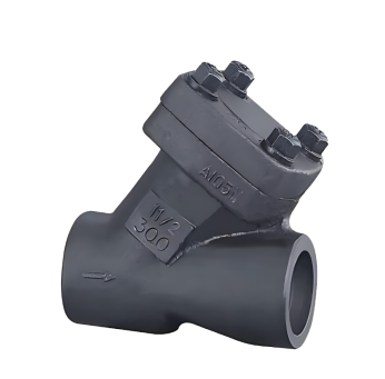
H61Y Forged Steel Y-Type Check Valve Product Image
H61Y Forged Steel Y-Type Check Valve Features
1. Y-Type Flow Path with Low Pressure Loss Design
The unique Y-shaped valve body structure ensures smooth directional change of the medium flow, significantly reducing fluid resistance and pressure loss. This makes it particularly suitable for critical pipelines with high flow velocities or sensitivity to system pressure drops.
2. Forged Steel Body with High-Pressure Performance
The valve is integrally forged, providing dense and uniform material properties free from casting defects. Its exceptionally high mechanical strength ensures reliable operation under high pressure, high temperature, and frequent pressure fluctuations.
3. Wear-Resistant Hard Metal Sealing
The disc and seat feature hard alloy sealing surfaces, offering excellent resistance to erosion, high temperatures, and wear. This ensures long-lasting sealing reliability even under demanding operating conditions.
4. Rapid Closure and Compact Structure
Typically equipped with an auxiliary closing spring, the valve responds quickly and effectively prevents water hammer. Its compact design, with a shorter installation length compared to traditional right-angle check valves, saves valuable space.
5. Reliable Connections and Easy Maintenance
Available with internal thread or butt-weld connections for dependable sealing. The structural design facilitates online inspection or maintenance, and some models support quick replacement of internal sealing components.
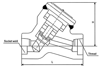
H61Y Forged Steel Y-Type Check Valve Structure Diagram
Parts Name Material List
| 序 号NO. | 名称Name | 材料Material |
| 5 | 垫片gasket | 316夹柔性石墨、316夹PTFE 316 +graphte 316 + PTFE |
| 4 | 螺栓bolt | B7、B8、B16 |
| 3 | 阀瓣disc | 碳钢、不锈钢Stainless Steel, Carbon Steel |
| 2 | 阀盖bonnet | 碳钢、不锈钢Stainless Steel, Carbon Steel |
| 1 | 阀体body | 碳钢、不锈钢Stainless Steel, Carbon Steel |
| 性能规范表Performance Specification | ||
| 公称压力Nominal Pressure | 2.0-15 | Mpa |
| 强度试验压力Shell Test | 3-22.5 | |
| 密封试验压力Seal Test | 2.2-16.5 | |
| 适用温度Suitable Temp. | ≤550 | ℃ |
Dimensions Standard Requirements
1. The structural length of the valve shall conform to the standard GB/T 12221.
2. The connecting flange shall conform to the standard JB/T 3595.

H61Y Forged Steel Y-Type Check Valve View Drawing
H61Y Forged Steel Y-Type Check Valve Dimensions Table
| 口径SIZE | RB缩径L | RB缩径H | FB全径L | FB全径H |
| DN10 | 98 | 85 | 98 | 85 |
| DN15 | 98 | 85 | 110 | 95 |
| DN20 | 110 | 95 | 120 | 105 |
| DN25 | 120 | 105 | 140 | 114 |
| DN32 | 140 | 114 | 140 | 114 |
| DN40 | 140 | 114 | 170 | 132 |
| DN50 | 170 | 132 | 200 | 145 |
-
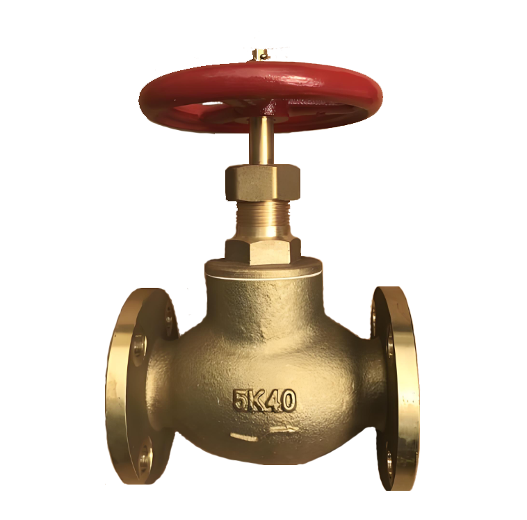 JIS Brass Stop-Check Valve
Model:
JIS F7301/F7352Specification:
DN15-DN80Pressure:
5K,10KMaterial:
Brass -
 H42W Vertical Check Valve
Model:
H42W-16C/H42W-25P/H42W-40P/H42W-20RSpecification:
DN25-200Pressure:
PN16,PN25,PN40Material:
Carbon Steel, Stainless Steel -
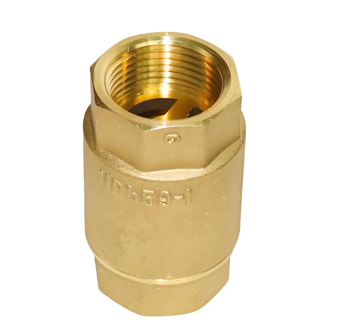 H12W Internal Thread Brass Lift Check Valve
Model:
H12W-10T/H12W-16T/H12W-25T/H12W-40TSpecification:
DN15-50Pressure:
PN10,PN16,PN25,PN40Material:
brass

Complete Guide to Check Valve Selection and Installation: Detailed Explanation of Principles, Selection, and Key Construction Points Check valves, as crucial safety components in pipeline systems, are essential for preventing medium backflow and ensuring safe system operation. This article will provide you with a comprehensive guide to the selection and installation of check valves.
1. Operating Principle and Classification of Check Valves 1.1 What is a Check Valve?
Check valves, also known as one-way valves or non-return valves, belong to the category of automatic valves. Their working principle is to achieve opening and closing through the flow force of the medium itself. Their core function is to prevent the reverse flow of pipeline medium and ensure one-way flow.
1.2 Main application scenario: foot valve (a special type of check valve) at the water pump suction inlet
Various pipeline systems requiring unidirectional flow of medium
Industrial settings where accidents caused by medium backflow are to be prevented
II. Selection Criteria and Guidelines for Check Valves 2.1 Basic Selection Principles Medium Adaptability: Suitable for clean medium conditions, not recommended for pipelines containing solid particles or high viscosity media.
2.2 Selection of pipeline size (DN) based on pipeline size. Recommended valve types. Applicable pressure range: DN<50mm. Butterfly check valve, vertical lift check valve, diaphragm check valve. Low-pressure environment: 50mm
Advantages: Effectively eliminates the water hammer phenomenon
Limitations: Subject to temperature and pressure constraints, suitable for low-pressure and normal-temperature pipelines
Applicable scenario: Water supply pipelines prone to water hammer
Slow-closing check valve:
Slow-closing swing check valve
Slow-closing butterfly check valve
Applicable scenario: pipeline systems that require minimal or no water hammer impact when shut down
III. Installation specifications and construction requirements for check valves 3.1 Preparatory work before installation Appearance inspection:
Check the valve nameplate information to ensure compliance with the GB 12220 "General Valve Marking" standard
Check the integrity of the valve and confirm that it is undamaged
Pressure test requirements:
If the working pressure exceeds 1.0 MPa or the main pipe shut-off valve is involved, a pressure test must be conducted
Strength test: Nominal pressure × 1.5, duration ≥ 5 minutes, no leakage is considered as qualified
Tightness test: nominal pressure × 1.1, determine the duration according to GB 50243 standard
3.2 Installation location and direction: Strictly follow the design drawings to determine the location, height, and inlet and outlet directions
Flow direction indicator: Ensure that the flow direction of the medium is completely consistent with the direction indicated by the arrow on the valve body
Pipe support:
It is prohibited to let the check valve bear the weight of the pipeline
Large check valves must be equipped with independent support structures
Avoid direct impact of piping pressure on the valve
3.3 Lift check valves are required for specific types of installations:
Vertical flap type: It must be installed on a vertical pipeline
Horizontal flap type: It must be installed on a horizontal pipeline
Swing check valve:
Ensure that the valve disc's rotating shaft is in a horizontal position during installation
Special attention should be paid to the flow direction of the medium during inclined installation
IV. Common Installation Errors and Precautions 4.1 Example of Incorrect Installation: Installing a Vertical Lift Check Valve on a Horizontal Pipe
The valve flow direction is reversed
Large valves have no independent support
Pressure testing was not conducted according to specifications
4.2 The selection and installation location of check valves should be considered during the design phase of the professional advice system
Provide complete operating condition parameters to the supplier during procurement to obtain professional selection advice
For complex systems, it is recommended to consult a professional valve engineer
Conduct regular maintenance and inspection to ensure the check valve operates in normal condition
5. Maintenance points: Regularly check whether the valve can be opened and closed flexibly
Monitor for abnormal sounds, such as water hammer impact
Check the sealing performance to prevent internal leakage
Lubricate the moving parts to ensure normal operation
The correct selection and installation of check valves are crucial for ensuring the safe operation of pipeline systems. Following the selection guidelines and installation specifications provided in this article can prevent various accidents caused by medium backflow, extend the service life of valves, and reduce maintenance costs.
In practical applications, it is recommended to consider specific engineering requirements and medium characteristics, and if necessary, consult professional valve technicians to ensure the optimization of the selection and installation plan.
Address:No. 1, Linxia Road, Sanqiao Industrial Zone, Oubei Sub-district, Yongjia County, Zhejiang Province| Switchboard:0577-67198981| mobile:+8613388552747| Email:sales@shanliuvalve.com|
COPYRIGHT © Zhejiang Shanliu Valve Technology Co., Ltd. Main Business: Water Valve Industrial valve|
浙ICP备2026020749号![]()