Your location:
 /
valves
/
Pressure Reducing Valve
/
Water Pressure Reducing Valve
/
200X Water Pressure Reducing Valve
/
valves
/
Pressure Reducing Valve
/
Water Pressure Reducing Valve
/
200X Water Pressure Reducing Valve

Mark Classification of Fluid products
- Phone:+86(577)67198981
- Fax:+86(577)67038872
- mobile:+8613388552747
- Sales Email 1:Karrie@shanliuvalve.com
- Sales Email 2:Yannie@shanliuvalve.com
- Sales Email 3:Merry@shanliuvalve.com
- Sales Email 4:Lucas@shanliuvalve.com
- Email:sales@shanliuvalve.com

200X Water Pressure Reducing Valve
- Model:200X-10/200X-16/200X-25/200X-10C/200X-16C/200X-25C/200X-10T/200X-16T/200X-25T/200X-10P/200X-16P/200X-25P
- Specification:DN50-DN800
- Temperature:≤ 80 ℃
- Medium:Water and water-like media
- Pressure:PN10,PN16,PN25
- Connection method:Flange
- Driving method:Automated
- Material:Cast Iron、Cast Steel、Stainless Steel、brass


Add QR code to serve you!
- Product Overview
- Performance Data
- Size Weight
200X Water Pressure Reducing Valve Overview
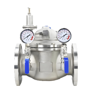
The 200X Water Pressure Reducing Valve is an automatically controlled valve that adopts a pilot-piston design, specifically used to stabilize and reduce downstream water pressure in water supply systems. The valve utilizes a pilot valve to sense downstream pressure changes, driving the main valve disc via a piston or diaphragm to automatically adjust the opening degree of the valve port. This allows fluctuating inlet pressure to be reduced to a set, stable outlet pressure. The valve body is typically made of brass, cast iron, or stainless steel, making it suitable for both cold and hot water systems. This valve effectively eliminates water hammer, reduces noise, and protects downstream pipelines and equipment. It is widely used in building water supply, fire protection systems, regional water supply, industrial circulating water systems, and other pipeline applications.
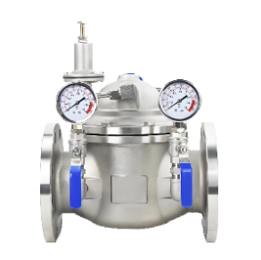
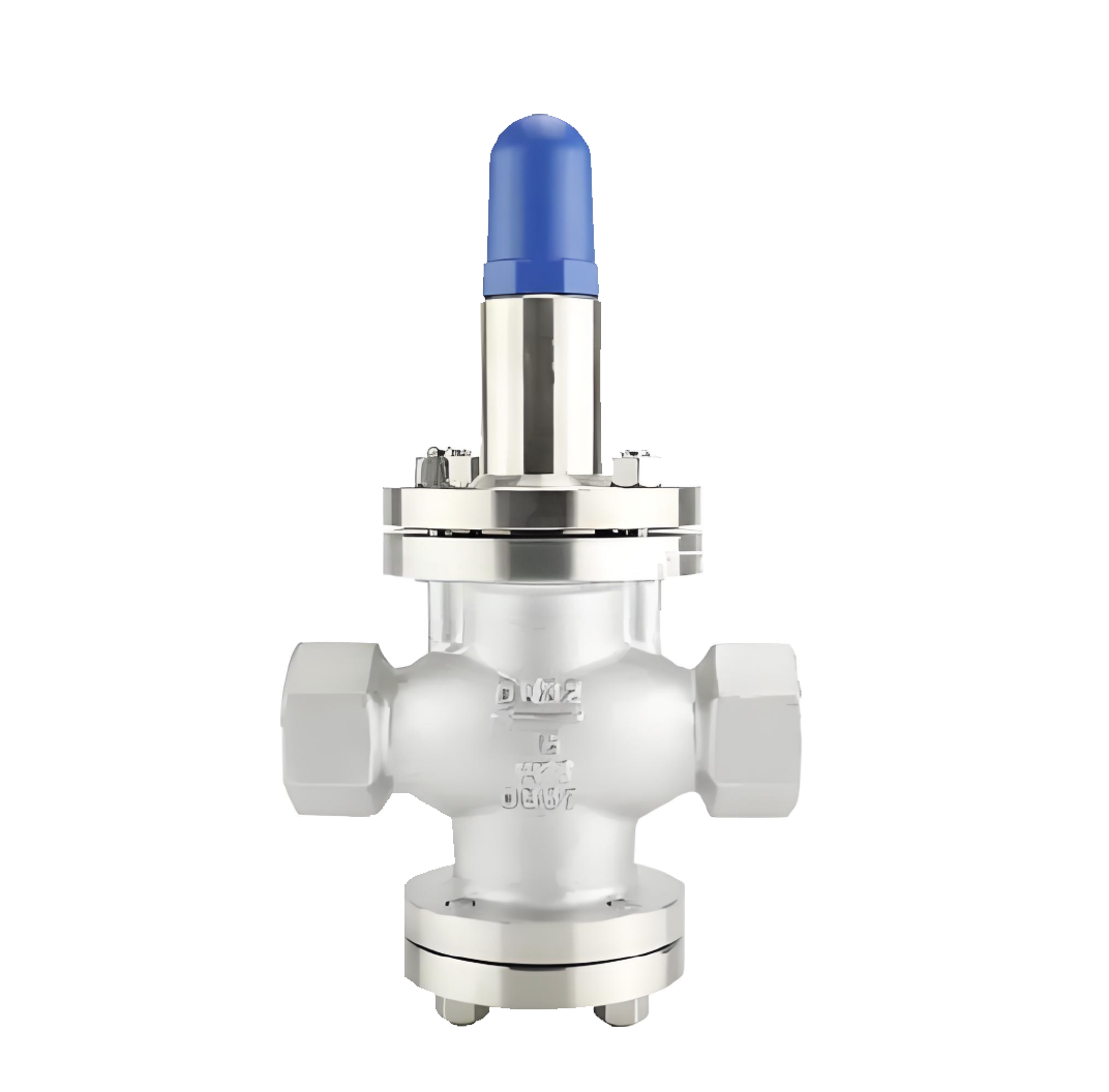
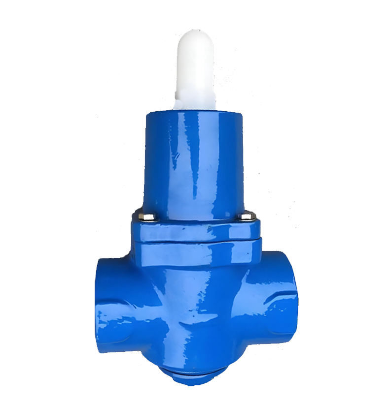
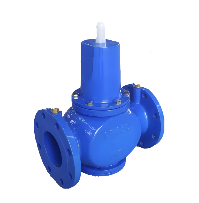
200X Water Pressure Reducing Valve Product Image
200X Water Pressure Reducing Valve Features
1. Accurate and Stable Pressure Reduction Performance: Utilizing a pilot-operated control principle, it responds sensitively to downstream pressure changes, precisely maintaining the outlet pressure at the set value with minimal fluctuation and high stability.
2. Automatic Adjustment and Wide Pressure Range: When the inlet pressure varies within a certain range, the valve automatically and continuously adjusts to keep the outlet pressure constant. It typically features a high pressure reduction ratio and is suitable for a wide range of pressure conditions.
3. Reliable Structure and Easy Maintenance: The separate design of the main valve and pilot valve results in low failure rates. A strainer protects the pilot system, and key components such as diaphragms and O-rings are easy to inspect and replace.
4. Water Hammer Elimination and Low Noise: Its smooth regulating action effectively prevents sudden pressure changes, significantly reducing water hammer effects and fluid noise, thereby protecting the pipeline system.
5. Flexible Installation and Wide Applicability: It can be installed horizontally or vertically (specific models required), with flange or threaded connections available. Suitable for domestic water supply, firefighting, irrigation, and various industrial water systems, offering high cost-effectiveness.
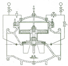
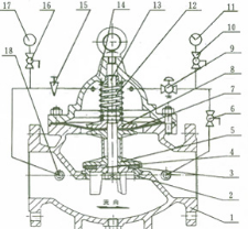
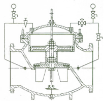
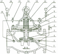
200X Water Pressure Reducing Valve Structure Diagram
Parts Name Material List
| 序 号NO. | 名称Name | 材料Material |
| 1 | 阀 体body | 铸铁、铸钢、不锈钢Cast Iron, Cast Steel, Stainless Steel |
| 2 | 阀 座seat | 铜、不锈钢Copper, Stainless Steel |
| 3 | 密封垫gasket | 强化橡胶Reinforced Rubber |
| 4 | 密封垫压板密封垫压板 Gasket Pressure Plate | 铜、不锈钢Copper, Stainless Steel |
| 5 | 阀 盘 disc | 铜、不锈钢Copper, Stainless Steel |
| 6 | 球 阀ball valve | 铜Copper |
| 7 | 膜 片diaphragm | 强化橡胶Reinforced Rubber |
| 8 | 膜片压板Diaphragm Pressure Plate | 铜、不锈钢Copper, Stainless Steel |
| 9 | 导 阀导阀 Pilot Valve | 铜Copper |
| 10 | 球 阀ball valve | 铜Copper |
| 11 | 压力表Pressure Gauge | |
| 12 | 压缩弹簧Compression Spring | 不锈钢Stainless Steel |
| 13 | 阀 杆Stem | 不锈钢Stainless Steel |
| 14 | 阀 盖bonnet | 铸铁、铸钢、不锈钢Cast Iron, Cast Steel, Stainless Steel |
| 15 | 针 阀needle valve | 铜Copper |
| 16 | 球 阀ball valve | 铜Copper |
| 17 | 压力表Pressure Gauge | |
| 18 | 微型过滤器Micro Filter | 不锈钢Stainless Steel |
| 性能规范表Performance Specification | ||
| 公称压力Nominal Pressure | 1.0/1.6/2.5 | Mpa |
| 强度试验压力Shell Test | 1.5/2.4/3.75 | |
| 密封试验压力Seal Test | 1.1/1.76/2.75 | |
| 适用温度Suitable Temp. | ≤80 | ℃ |
Dimensions Standard Requirements
1. The structural length of the valve shall conform to the standard GB/T12221.
2. The connecting flange shall conform to the standard GB/T 17241.6
200X Water Pressure Reducing Valve View Drawing
200X Water Pressure Reducing Valve Dimensions Table
| 公称通径 | 尺 寸 (mm) | ||||||||||||||||
| L | D | D1 | D2 | Z-фd | F1 | F | H1 | H | |||||||||
| PN10 | PN16 | PN25 | PN10 | PN16 | PN25 | PN10 | PN16 | PN25 | PN10 | PN16 | PN25 | ||||||
| 50 | 240 | 165 | 165 | 165 | 125 | 125 | 125 | 102 | 102 | 99 | 4-18 | 4-18 | 4-18 | 155 | 330 | 278 | 395 |
| 65 | 250 | 185 | 185 | 185 | 145 | 145 | 145 | 122 | 122 | 118 | 4-18 | 4-18 | 8-φ18 | 165 | 350 | 298 | 405 |
| 80 | 255 | 200 | 200 | 200 | 160 | 160 | 160 | 133 | 133 | 132 | 8-418 | 8-Φ18 | 8-18 | 175 | 365 | 313 | 430 |
| 100 | 360 | 220 | 220 | 235 | 180 | 180 | 190 | 158 | 158 | 156 | 8-18 | 8-Φ18 | 8-Φ22 | 195 | 410 | 350 | 510 |
| 125 | 400 | 250 | 250 | 270 | 210 | 210 | 220 | 184 | 184 | 184 | 8-Φ18 | 8-Φ18 | 8-226 | 220 | 455 | 365 | 560 |
| 150 | 455 | 285 | 285 | 300 | 240 | 240 | 250 | 212 | 212 | 211 | 8-Φ22 | 8-22 | 8-Φ26 | 230 | 475 | 420 | 585 |
| 200 | 585 | 340 | 340 | 360 | 295 | 295 | 310 | 268 | 268 | 274 | 8-Φ22 | 12-422 | 12-426 | 255 | 530 | 450 | 675 |
| 250 | 650 | 395 | 405 | 425 | 350 | 355 | 370 | 320 | 320 | 330 | 12-Φ22 | 12-+26 | 12-430 | 300 | 623 | 470 | 730 |
| 300 | 800 | 445 | 460 | 485 | 400 | 410 | 430 | 370 | 370 | 389 | 12422 | 12426 | 16-+30 | 340 | 700 | 490 | 760 |
| 350 | 860 | 505 | 520 | 555 | 460 | 470 | 490 | 430 | 430 | 448 | 16-+22 | 16-φ26 | 16-φ33 | 415 | 840 | 526 | 840 |
| 400 | 960 | 565 | 580 | 620 | 515 | 525 | 550 | 482 | 482 | 503 | 16-426 | 16-430 | 16-136 | 430 | 880 | 570 | 910 |
| 公 称 通 径 DN(mm ( | 尺 寸 ( m m ) | ||||||||||||
| L | D | D1 | D2 | Z-фd | H | H1 | B | F | |||||
| PN10 | PN16 | PN1 0 | PN1 6 | PN1 0 | PN1 6 | PN10 | PN16 | ||||||
| 350 | 860 | 505 | 520 | 460 | 470 | 430 | 438 | 16-φ2 2 | 16-φ2 6 | 340 | 495 | 650 | 640 |
| 400 | 960 | 565 | 580 | 515 | 525 | 482 | 490 | 16-φ2 6 | 16-φ3 0 | 380 | 550 | 730 | 715 |
| 450 | 1075 | 615 | 640 | 565 | 585 | 532 | 550 | 20-φ2 6 | 20-φ3 0 | 420 | 610 | 800 | 780 |
| 500 | 1075 | 670 | 715 | 620 | 650 | 585 | 610 | 20-φ2 6 | 20-φ3 3 | 470 | 665 | 880 | 830 |
| 600 | 1230 | 780 | 840 | 725 | 770 | 685 | 725 | 20-φ3 0 | 20-φ3 6 | 545 | 725 | 980 | 880 |
| 700 | 1650 | 895 | 910 | 840 | 840 | 800 | 795 | 24-φ3 0 | 24-φ3 6 | 595 | 865 | 1150 | 980 |
| 800 | 1750 | 1015 | 1025 | 950 | 950 | 905 | 900 | 24-φ3 3 | 24-φ3 9 | 665 | 975 | 1300 | 1050 |
-
 Y12H Diaphragm Stainless Steel Pressure Reducing Valve
Model:
Y12H-16P/Y12H-25PSpecification:
DN15-DN50Pressure:
PN16,PN25Material:
Stainless steel -
 Y11X Direct-Acting NPT Pressure Reducing Valve
Model:
Y11X-10Q/Y11X-16Q/Y11X-10/Y11X-16Specification:
DN15-DN50Pressure:
PN10,PN16Material:
ductile iron、Grey Cast Iron -
 Y41X Adjustable Pressure Reducing Valve
Model:
Y41X-16/Y41X-25/Y41X-16C/Y41X-25CSpecification:
DN125-DN400Pressure:
PN16,PN25Material:
Cast iron、ductile iron、carbon steel

Is the noise from the pressure reducing valve disturbing? Understand the 3 fundamental reasons and solutions in one article
The harsh noise generated by pressure reducing valves during operation is not only an environmental pollution problem, but also a precursor to equipment failure. This article will delve into the three fundamental causes of noise generated by pressure reducing valves - mechanical vibration noise, fluid dynamics noise, and aerodynamic noise, and provide professional solutions.
1、 Mechanical vibration noise: a test of design and process
Mechanical vibration noise is the most common type of noise in pressure reducing valves, mainly divided into two forms:
1. Low frequency vibration noise
Causes:
Medium jet and pressure pulsation
The outlet flow rate of the valve is too fast
Unreasonable pipeline layout
Insufficient rigidity of moving parts inside the valve
2. High frequency vibration noise (resonance phenomenon)
Causes:
The natural frequency of the valve coincides with the excitation frequency of the medium
Easy to occur within a specific decompression range
Sensitive to changes in working conditions, with significant noise fluctuations
Solution:
Optimize the clearance design between the liner and valve stem
Improve machining accuracy
Adjust the natural frequency of the valve
Enhance the rigidity of active components
Select appropriate damping materials
2、 Fluid Dynamics Noise: Challenges in Fluid Control
The turbulence and eddies generated when the fluid passes through the pressure reducing valve can cause significant noise problems.
1. Turbulent noise
Features: Low frequency, low noise level
Cause: Interaction between turbulent fluid and the inner surface of valves/pipelines
Impact: Usually does not constitute a serious noise problem
2. Cavitation noise (the most harmful)
Production mechanism:
During the depressurization process, the fluid flow velocity reaches the critical value
The liquid begins to vaporize, producing bubbles
Bubble explosion under pressure generates shock waves
Local instantaneous pressure can reach 196 MPa
Key data:
Initial value of Δ p: the critical pressure reduction value at which liquid begins to cavitation
Exceeding this value leads to a sharp increase in noise
Preventive measures:
Control the actual pressure reduction value below the critical value
Optimize the design of valve disc fluid direction
Adopting a multi-stage decompression structure
Choose anti cavitation materials
3、 Aerodynamic noise: characteristics of compressible fluids
When compressible fluids such as steam pass through pressure reducing areas, unique noise issues arise:
Production principle:
Conversion of fluid mechanical energy into sound energy
Interaction between high-speed airflow and valve structure
Sudden pressure changes cause gas expansion and sound emission
Control method:
Optimize the design of pressure reducing flow channels
Using mufflers or diffusers
Control the outlet flow rate
Reasonably set back pressure
Comprehensive solutions and selection suggestions
Preventive measures during the design phase
Parameter optimization: Accurately calculate operating parameters to ensure that the pressure reduction value is within the design range
Structural design: Adopting streamlined flow channels to reduce turbulence generation
Material selection: Select special alloys with high rigidity and cavitation resistance
Frequency analysis: avoid the natural frequency of the valve coinciding with the excitation frequency
Key points for installation and maintenance
Correct installation: Ensure the length of the front and rear straight pipe sections to avoid sharp bends
Regular testing: Establish a noise monitoring mechanism to detect problems early on
Timely maintenance: replace worn parts and maintain the best condition of the valve
Brand selection recommendation
High pressure differential operating condition: choose multi-stage pressure reducing valve
Liquid medium: focus on anti cavitation design
Gas/Steam: Focus on Aerodynamic Optimization
Sensitive environment: Choose a low-noise dedicated model
Professional Technical Summary
The essence of the noise problem of pressure reducing valves is the process of energy conversion and release. Fundamentally, all noise issues are closely related to the rationality of valve design, manufacturing process accuracy, and compatibility with operating conditions. Through scientific selection, correct installation, and standardized maintenance, it is entirely possible to control the noise of the pressure reducing valve within an acceptable range.
Immediate action suggestion: If you are troubled by pressure reducing valve noise, it is recommended to first record the noise characteristics (frequency, time period, change pattern), check whether the operating parameters deviate from the design values, and promptly contact professional technicians for diagnosis and treatment.
Keywords of this article: pressure reducing valve noise, mechanical vibration noise, cavitation noise, fluid dynamics noise, pressure reducing valve failure, valve noise reduction, industrial noise control, equipment maintenance
Extended reading: For more professional knowledge about industrial valve selection and maintenance, please follow our technical column to obtain the latest solutions and industry practice cases.
Address:No. 1, Linxia Road, Sanqiao Industrial Zone, Oubei Sub-district, Yongjia County, Zhejiang Province| Switchboard:0577-67198981| mobile:+8613388552747| Email:sales@shanliuvalve.com|
COPYRIGHT © Zhejiang Shanliu Valve Technology Co., Ltd. Main Business: Water Valve Industrial valve|
浙ICP备2026020749号![]()