Your location:
 /
valves
/
industrial valve
/
Globe valve
/
J641H Pneumatic Stop Valve
/
valves
/
industrial valve
/
Globe valve
/
J641H Pneumatic Stop Valve

Mark Classification of Fluid products
- Phone:+86(577)67198981
- Fax:+86(577)67038872
- mobile:+8613388552747
- Sales Email 1:Karrie@shanliuvalve.com
- Sales Email 2:Yannie@shanliuvalve.com
- Sales Email 3:Merry@shanliuvalve.com
- Sales Email 4:Lucas@shanliuvalve.com
- Email:sales@shanliuvalve.com

J641H Pneumatic Stop Valve
- Model:J641H-16C/J641H-25C/J641H-40C/J641H-16P/J641H-25P/J641H-40P/J641H-16R/J641H-25R/J641H-40R
- Specification:DN50-DN200
- Temperature:≤ 450 ℃
- Medium:Water, steam, oil and similar liquids, gases
- Pressure:PN16~PN40
- Connection method:flange
- Driving method: Pneumatic
- Material:Cast steel, stainless steel


Add QR code to serve you!
- Product Overview
- Performance Data
- Size Weight
Overview
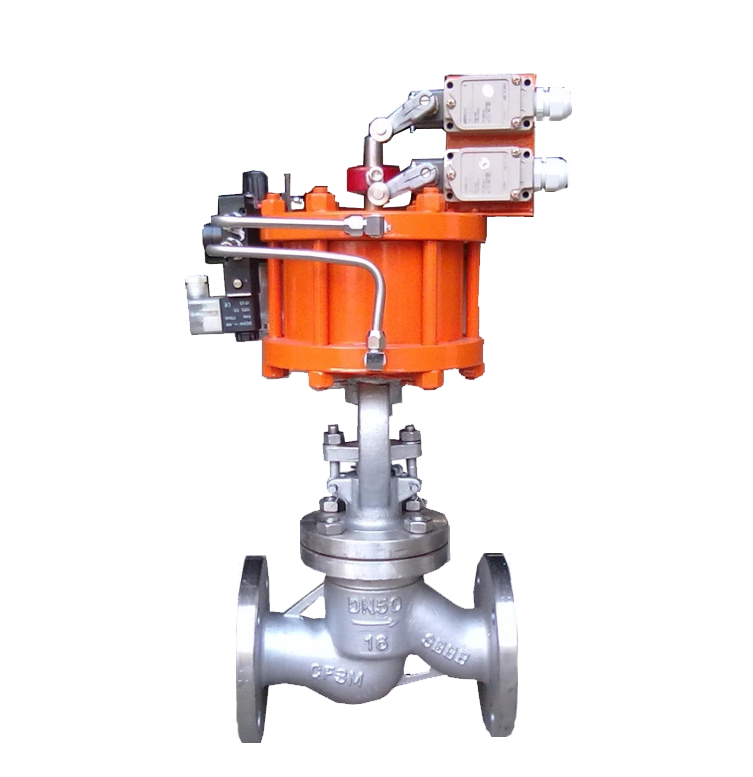
J641H pneumatic globe valve is a valve that opens, closes, and regulates fluid channels by driving the valve disc (gate) vertically up and down along the centerline of the valve seat channel through the valve stem. The sealing pair (valve disc and valve seat) adopts a metal hard sealing structure, usually welded or embedded with hard alloy, which has the characteristics of high hardness, wear resistance, and high temperature resistance. The valve is connected by flanges and fixed to the pipeline flange with bolts. Valves rely on pneumatic devices (usually cylinders or piston actuators) to drive the valve stem, converting the energy of compressed air into linear thrust, thereby quickly and reliably controlling the opening, closing, or positioning of the valve disc. This valve is particularly suitable for working conditions with high temperature, high pressure, and strict sealing requirements.

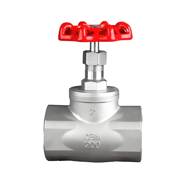
J641H Pneumatic Stop Valve Product Drawing
feature
1. High sealing reliability: Adopting a metal hard sealing structure, the sealing surface between the valve disc and the valve seat is usually welded with hard alloy and precision ground. Under the high-pressure thrust of the pneumatic actuator, it can achieve a tight metal wire seal with a high sealing level, suitable for harsh working conditions such as high temperature, high pressure, and zero leakage requirements.
2. Smooth opening and closing, precise adjustment: When the valve is opened and closed, the valve disc moves vertically in a straight line without any obstruction. With the precise control of pneumatic actuators (which can be equipped with attachments such as locators), accurate flow regulation and stable and reliable switch positioning can be achieved, especially suitable for automation systems that require process control.
3. High temperature, high pressure and erosion resistance: The sturdy rigid structure, high temperature resistant metal valve body and hard alloy sealing surface enable the valve to withstand high system pressure and temperature, and have good anti erosion and wear resistance to steam, high-speed fluids and media with small particles.
4. High fluid resistance: Due to the non straight passage in the valve chamber, the medium needs to change direction (in an "S" shape), resulting in a high flow resistance coefficient. In the fully open state, the pressure loss is higher than that of gate valves or ball valves of the same specifications.
5. Longer structural length: Compared with butterfly valves, ball valves, etc., globe valves have a higher structural height, longer structural length, larger volume and weight, and have certain requirements for installation space.
6. Automatic and efficient driving mode: It is driven by pneumatic actuators and uses compressed air as the power source. It has a fast response speed and can achieve remote centralized control, rapid opening and closing, or emergency shutdown. It is one of the key equipment for industrial automation pipeline control.
Structure Diagram of J641H Pneumatic Stop Valve
List of Component Names and Materials
| 阀体/阀盖Valve body/valve cover | 阀瓣valve disc | 密封圈sealing ring | 阀杆valve stem |
| WCB | WCB+D507MO | D577 | 2Crl3 |
| ZGlCrl8Ni9Ti | 0Crl8Ni9Ti Stellite12 | Stellite6 | lCrl8Ni9Ti |
| ZGlCrl8Ni2Mo2Ti | CF8M Stellite12 | lCrl8Ni2Mo2Ti | lCrl8Ni2Mo2Ti |
| ZG00Crl7Nil4M02 | CF3M Stellite12 | Stel1ite6 | 316L |
| ZGlCr5MO | ZGlCr5MO Stellite12 | Stel1ite6 | 25Cr2Mo1VA |
Performance Specification Sheet
| 性能规范表Performance Specification Sheet | ||
| 公称压力Nominal Pressure | 1.6/2.5/4.0 | MPa |
| 强度试验压力Strength test pressure | 2.4/3.75/6 | |
| 密封试验压力Sealing test pressure | 1.76/2.75/4.4 | |
| 适用温度Applicable Temperature | ≤450 | ℃ |

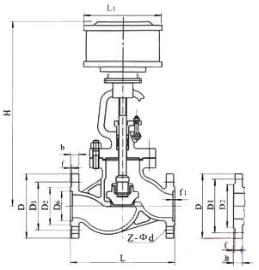
Outline Dimension Drawing of J641H Pneumatic Stop Valve
Outline Dimension Table of J641H Pneumatic Stop Valve
| 公称压力PN(MPa) | 公称通径DN(mm) | 标准值standard value | 参考值 reference value | ||||||||
| L | D | D1 | n2 | D6 | b | f | f1 | Z-φd | L1 | ||
| 1.6 | 50 | 230 | 160 | 125 | 100 | 16 | 3 | 4-φ18 | 185 | ||
| 65 | 290 | 180 | 145 | 120 | 18 | 3 | 4-φ18 | 232 | |||
| 80 | 310 | 195 | 160 | 135 | 20 | 3 | 8-φ18 | 232 | |||
| 100 | 350 | 215 | 180 | 155 | 20 | 3 | 8-φ18 | 232 | |||
| 125 | 400 | 254 | 210 | 185 | 22 | 3 | 8-φ18 | 283 | |||
| 150 | 480 | 280 | 240 | 210 | 24 | 3 | 8-φ23 | 283 | |||
| 200 | 600 | 335 | 295 | 265 | 26 | 3 | 12-φ23 | 283 | |||
| 250 | 622 | 405 | 355 | 320 | 30 | 3 | 12-φ25 | 283 | |||
| 300 | 698 | 460 | 410 | 375 | 30 | 4 | 12-φ25 | 283 | |||
| 2.5 | 50 | 230 | 160 | 125 | 100 | 20 | 3 | 4-φ18 | 185 | ||
| 65 | 290 | 180 | 145 | 120 | 22 | 3 | 8-φ18 | 232 | |||
| 80 | 310 | 195 | 160 | 135 | 22 | 3 | 8-φ18 | 232 | |||
| 100 | 350 | 230 | 190 | 160 | 24 | 3 | 8-φ23 | 232 | |||
| 125 | 400 | 270 | 220 | 188 | 28 | 3 | 8-φ25 | 283 | |||
| 150 | 480 | 300 | 250 | 218 | 30 | 3 | 8-φ25 | 283 | |||
| 200 | 600 | 360 | 310 | 278 | 34 | 3 | 12-φ25 | 283 | |||
| 250 | 622 | 425 | 370 | 332 | 36 | 3 | 12-φ30 | 283 | |||
| 300 | 698 | 485 | 430 | 390 | 40 | 4 | 16-φ30 | 283 | |||
| 4.0 | 50 | 230 | 160 | 125 | 100 | 88 | 20 | 3 | 4 | 4-φ18 | 185 |
| 65 | 290 | 180 | 145 | 120 | 110 | 22 | 3 | 4 | 8-φ18 | 232 | |
| 80 | 310 | 195 | 160 | 135 | 121 | 22 | 3 | 4 | 8-φ18 | 232 | |
| 100 | 350 | 230 | 190 | 160 | 150 | 24 | 3 | 4.5 | 8-φ23 | 232 | |
| 125 | 400 | 270 | 220 | 188 | 176 | 28 | 3 | 4.5 | 8-φ25 | 283 | |
| 150 | 480 | 300 | 250 | 218 | 204 | 30 | 3 | 4.5 | 8-φ25 | 283 | |
| 200 | 600 | 375 | 320 | 282 | 260 | 38 | 3 | 4.5 | 12-φ30 | 283 | |
-
 JY4N Russian Standard Gas Stop Valve
Model:
JY41N-16C/JY41N-25C/JY41N-40C/JY41N-64C/JY41N-16P/JY41N-25P/JY41N-40P/JY41N-64PSpecification:
DN50~DN300Pressure:
PN16-PN64Material:
Cast Steel, Stainless Steel -
 J45F46 fluorine lined DC globe valve
Model:
J45F46-10C/J45F46-16CSpecification:
DN15-DN300Pressure:
PN10-PN16Material:
Cast steel + PTFE (Teflon) -
 J11W American Standard Internal Thread Globe Valve
Model:
J11W-10P/J11W-16P/J11W-25PSpecification:
DN15-DN50Pressure:
PN10-PN25Material:
Stainless steel
Address:No. 1, Linxia Road, Sanqiao Industrial Zone, Oubei Sub-district, Yongjia County, Zhejiang Province| Switchboard:0577-67198981| mobile:+8613388552747| Email:sales@shanliuvalve.com|
COPYRIGHT © Zhejiang Shanliu Valve Technology Co., Ltd. Main Business: Water Valve Industrial valve|
浙ICP备2026020749号![]()