Your location:
 /
valves
/
industrial valve
/
Globe valve
/
J641W Pneumatic Manual Stop Valve
/
valves
/
industrial valve
/
Globe valve
/
J641W Pneumatic Manual Stop Valve

Mark Classification of Fluid products
- Phone:+86(577)67198981
- Fax:+86(577)67038872
- mobile:+8613388552747
- Sales Email 1:Karrie@shanliuvalve.com
- Sales Email 2:Yannie@shanliuvalve.com
- Sales Email 3:Merry@shanliuvalve.com
- Sales Email 4:Lucas@shanliuvalve.com
- Email:sales@shanliuvalve.com


J641W Pneumatic Manual Stop Valve
- Model:J641W-16C/J641W-25C/J641W-40C/J641W-16P/J641W-25P/J641W-40P/J641W-16R/J641W-25R/J641W-40R/
- Specification:DN20-DN100
- Temperature:≤ 450 ℃
- Medium:Water, steam, oil and similar liquids, gases
- Pressure:PN16~PN40
- Connection method:flange
- Driving method: Pneumatic
- Material:Cast steel, stainless steel


Add QR code to serve you!
- Product Overview
- Performance Data
- Size Weight
Overview
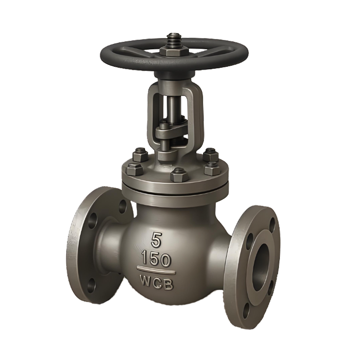
The J641W Pneumatic Manual Stop Valve is a valve that opens, closes, and regulates fluid flow by using a stem to drive the disc (gate) in a vertical lifting motion along the centerline of the seat passage. Its sealing pair (disc and seat) utilizes a metal-to-metal hard seal structure, typically hardfaced or inserted with cemented carbide, featuring high hardness, wear resistance, and high-temperature resistance. The valve uses a flange connection, secured to the pipeline flange with bolts. The valve relies on a pneumatic device (typically a cylinder or piston actuator) to drive the stem, converting the energy of compressed air into linear thrust, thereby quickly and reliably controlling the opening, closing, or positioning of the disc. This valve is particularly suitable for high-temperature, high-pressure, and demanding sealing applications.
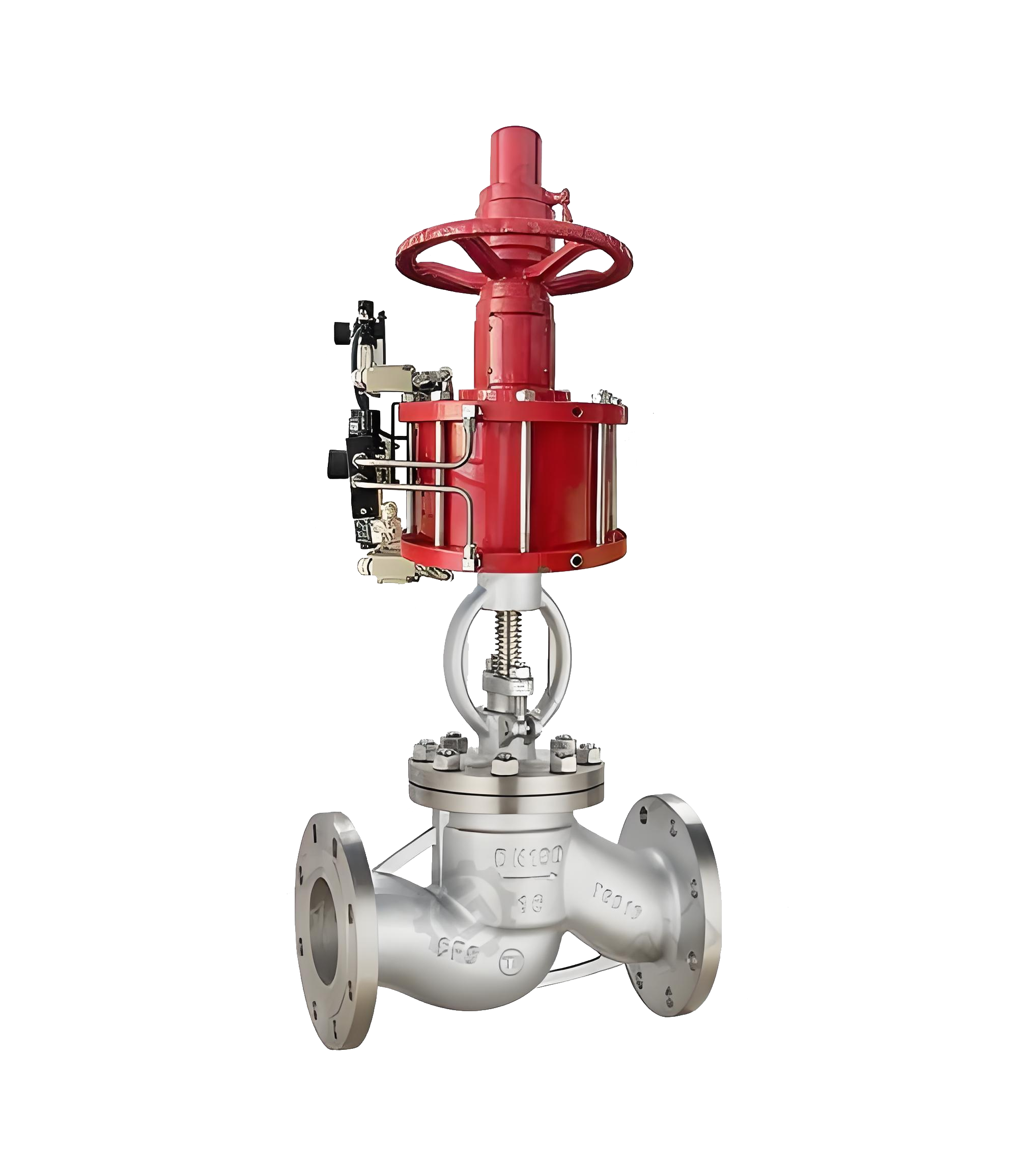
J641W Pneumatic Manual Stop Valve Product Image
Features
1、High Sealing Reliability: Utilizes a metal-to-metal hard seal structure. The sealing surfaces of the disc and seat are typically hardfaced with cemented carbide and precision-lapped. Under the high thrust of the pneumatic actuator, a tight metal-to-metal line seal is achieved. It offers high sealing performance, suitable for demanding applications involving high temperatures, high pressures, and requiring zero leakage.
2、Smooth Operation, Precise Regulation: During opening and closing, the disc moves in a precise vertical linear motion without binding. Combined with precise control from the pneumatic actuator (which can be equipped with accessories like positioners), it enables accurate flow regulation and stable, reliable on/off positioning, particularly suitable for automated systems requiring process control.
3、High Temperature, High Pressure, and Erosion Resistance: The robust rigid structure, high-temperature resistant metal body, and hardfaced alloy sealing surfaces enable the valve to withstand high system pressures and temperatures. It also offers good resistance to erosion and wear from steam, high-velocity fluids, and media containing small particles.
4、Higher Fluid Resistance: Due to the non-straight flow path inside the valve cavity, the medium must change direction (forming an "S" shape). Consequently, the flow resistance coefficient is higher, and the pressure loss in the fully open state is greater than that of gate valves or ball valves of the same size.
5、Longer Face-to-Face Dimensions: Compared to butterfly valves or ball valves, globe valves have a greater structural height, longer face-to-face dimensions, larger volume and weight, imposing certain requirements on installation space.
6、Automated and Efficient Drive Mode: Driven by a pneumatic actuator using compressed air as the power source. It offers fast response speed, enabling remote centralized control, rapid opening/closing, or emergency shut-off, making it a key equipment for industrial automated pipeline control.

J641W Pneumatic Stop Valve Structure Diagram
Part Name and Material List
| 阀体/阀盖Body / Bonnet | 阀瓣disc | 密封圈packing | 阀杆stem |
| WCB | WCB+D507MO | D577 | 2Crl3 |
| ZGlCrl8Ni9Ti | 0Crl8Ni9Ti Stellite12 | Stellite6 | lCrl8Ni9Ti |
| ZGlCrl8Ni2Mo2Ti | CF8M Stellite12 | lCrl8Ni2Mo2Ti | lCrl8Ni2Mo2Ti |
| ZG00Crl7Nil4M02 | CF3M Stellite12 | Stel1ite6 | 316L |
| ZGlCr5MO | ZGlCr5MO Stellite12 | Stel1ite6 | 25Cr2Mo1VA |
Performance Specification Table
| 公称通径DN(mm) | 20 | 25 | 32 | 40 | 50 | 65 | 80 | 100 | ||
| 额定流量系数KVRated flow coefficient KV | 7 | 11 | 20 | 30 | 48 | 75 | 120 | 190 | ||
| 额定行程Rated stroke(mm) | 8 | 12 | 20 | 25 | ||||||
| 气缸直径Cylinder bore diameter(mm) | 75 | 100 | 150 | |||||||
| 允许泄漏量Allowable leakage | 硬密封Hard seal(1/h) | 单座、三通:1.2X10⁻⁷X阀额定容量套简:5X10⁻⁶X阀额定容量Single seat, three-way: 1.2×10 – 7 × valve rated capacity Sleeve: 5×10 – 6 × valve rated capacity | ||||||||
| 软密封Soft seal | VI级 | |||||||||
| 工作温度Operating temperature(℃) | -20-200-40-450 | |||||||||
| 公称压力PN(MPa) | 1.6/4.0 | |||||||||
| 允许压差Allowable differential pressure(MPa) | ZSQP | 单作用Single-acting | 1.16 | 0.66 | 0.38 | 0.6 | 0.39 | 0.47 | 0.31 | 0.20 |
| 双作用Double-acting | 6.4 | 5.0 | 2.8 | 3.3 | 2.13 | 2.71 | 1.75 | 1.11 | ||
| ZSQM | 单作用Single-acting | 公称压力PN | ||||||||
| 双作用Double-acting | ||||||||||
| ZSQN | 单作用Single-acting | 0.89 | 0.57 | 0.35 | 0.56 | 0.36 | 0.45 | 0.30 | 0.20 | |
| 双作用Double-acting | 5.2 | 3.22 | 2.03 | 2.27 | 1.46 | 2.00 | 1.32 | 0.85 | ||
| 信号压力Signal pressure(kPa) | 0或400-600 | |||||||||
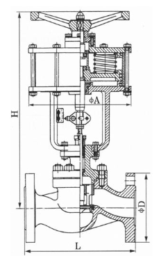
Outline Dimension Drawing of J641W Pneumatic Manual Stop Valve
Outline Dimension Table of J641W Pneumatic Manual Stop Valve
| 公称通径DN | L | A | H | L1 | H1 | A1 | 重量weight(Kg) | 信号接头内螺纹Signal connector internal thread |
| 20 | 150 | 130 | 220 | 80 | 115 | 100 | 10 | M10X1 |
| 25 | 160 | 130 | 220 | 80 | 120 | 100 | 12 | |
| 32 | 180 | 150 | 235 | 80 | 130 | 100 | 15 | |
| 40 | 200 | 150 | 235 | 95 | 138 | 120 | 18 | |
| 50 | 230 | 150 | 240 | 95 | 155 | 120 | 25 | |
| 65 | 290 | 280 | 250 | 105 | 178 | 160 | 30 | |
| 80 | 310 | 280 | 260 | 105 | 207 | 160 | 40 | |
| 100 | 350 | 280 | 265 | 105 | 222 | 160 | 60 |
-
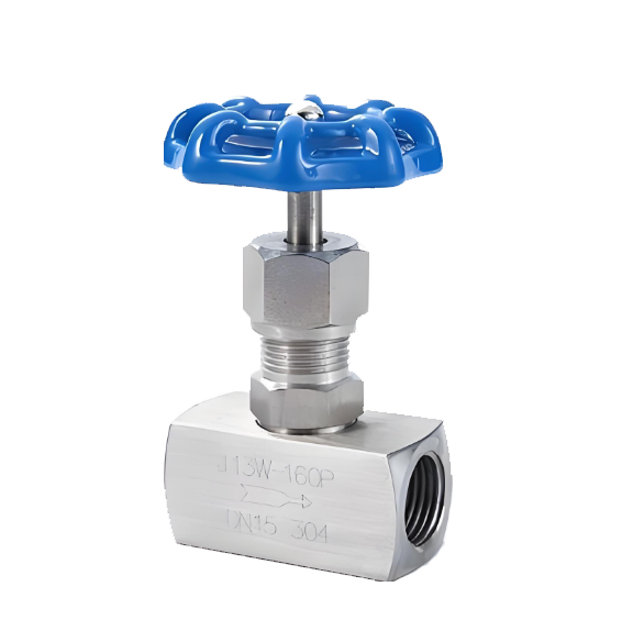 J13W needle type internal thread globe valve
Model:
J13W-25C/J13W-40C/J13W-64C/J13W-100C/J13W-160C/J13W-320C/J13W-25P/J13W-40P/J13W-64P/J13W-100P/J13W-160P/J13W-320P/J13W-25R/J13W-40R/J13W-64R/J13W-100R/J13W-160R/J13W-320RSpecification:
DN6-DN25Pressure:
PN25~PN320Material:
Forged steel, forged stainless steel -
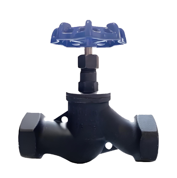 J11T Soviet-style internal thread stop valve
Model:
J11T-10/J11T-16Specification:
DN15~DN50Pressure:
PN10-PN16Material:
Cast iron -
 JIS Standard Stop-Check Valve
Model:
J41H-5K/J41H-10K/J41H-20K/J41Y-5K/J41Y-10K/J41Y-20KSpecification:
1/2”- 16”Pressure:
5K/10K/20KMaterial:
Cast steel, stainless steel
Address:No. 1, Linxia Road, Sanqiao Industrial Zone, Oubei Sub-district, Yongjia County, Zhejiang Province| Switchboard:0577-67198981| mobile:+8613388552747| Email:sales@shanliuvalve.com|
COPYRIGHT © Zhejiang Shanliu Valve Technology Co., Ltd. Main Business: Water Valve Industrial valve|
浙ICP备2026020749号![]()