Your location:
 /
valves
/
industrial valve
/
Globe valve
/
JIS Standard Stop Valve
/
valves
/
industrial valve
/
Globe valve
/
JIS Standard Stop Valve

Mark Classification of Fluid products
- Phone:+86(577)67198981
- Fax:+86(577)67038872
- mobile:+8613388552747
- Sales Email 1:Karrie@shanliuvalve.com
- Sales Email 2:Yannie@shanliuvalve.com
- Sales Email 3:Merry@shanliuvalve.com
- Sales Email 4:Lucas@shanliuvalve.com
- Email:sales@shanliuvalve.com

JIS Standard Stop Valve
- Model:J41W-5K/J41W-10K/J41W-20K
- Specification:DN15-DN200
- Temperature:-196~525℃
- Medium:Seawater, fresh water, oil, saturated gas
- Pressure:5K/10K/20K
- Connection method:flange
- Driving method:Handwheel
- Material:Aluminum nickel bronze


Add QR code to serve you!
- Product Overview
- Performance Data
- Size Weight
Overview
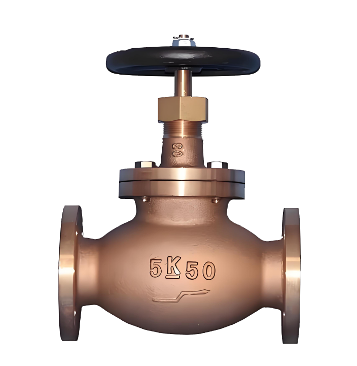
The JIS standard stop valve is a cast steel stop valve strictly designed and manufactured in accordance with Japanese Industrial Standards (JIS). It uses a handwheel or an electric device to drive the stem and disc in a vertical lifting motion along the centerline of the seat, achieving reliable opening and closing of the medium in the pipeline. The core of its design lies in the valve body, which is precision-cast using SCPH series carbon steel, SCS series stainless steel, or special alloys as specified in JIS G5151. This results in a compact structure, good rigidity, and reliable sealing. The valve seat sealing surface typically features a flat or conical design, with stainless steel or hard alloy overlay welding. Through precision grinding, a reliable metal-to-metal seal is achieved. The valve uses a flanged connection conforming to JIS B2220, fastened directly to the pipeline system flanges with bolts, offering high connection strength, reliable sealing, and convenient assembly and disassembly. The handwheel drives the stem, converting rotational force into the linear motion of the disc for smooth and reliable opening and closing control. This valve is specifically designed for pipeline systems handling steam, oil, water, and mildly corrosive media at operating temperatures ≤425°C. It is widely used in industrial pipelines requiring fluid shut-off or connection, such as in petrochemical, power generation, metallurgy, heating, and water supply & drainage industries. It is particularly suitable for JIS standard pipeline conditions with nominal pressures of 10K~20K and diameters DN15~DN200.

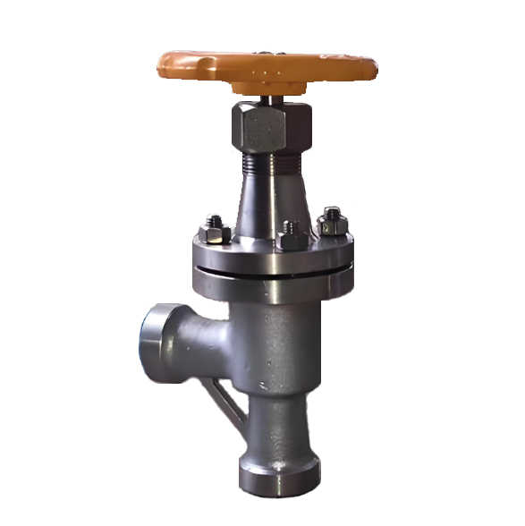
JIS Standard Stop Valve Product Image
Features
1.Strictly comply with JIS standards, suitable for Japanese market: Designed and manufactured in accordance with JIS B2002, JIS B2071, JIS B2220, fully compatible with Japanese and Southeast Asian markets following the JIS system.
2.Aluminum nickel bronze body, seawater corrosion resistant: Body precision cast from JIS ALBC3 aluminum nickel bronze, excellent resistance to seawater and chloride ion corrosion, suitable for severe corrosive conditions such as ships and offshore platforms.
3.Reliable sealing, high and low temperature resistant: Disc and seat sealing surfaces can be body seal (W), stainless steel overlay (H) or hard alloy overlay (Y), precision ground to achieve reliable metal-to-metal sealing, applicable temperature range -196℃~525℃.
4.Smooth flow path, strong flow capacity: Optimized flow path design, smooth medium flow, low pressure loss, stable and reliable opening and closing.
5.Flange connection, easy assembly and disassembly: Flange dimensions conform to JIS B2220 (10K/20K), bolted connection, reliable sealing, easy installation and maintenance.
6.Handwheel operation, easy to operate: Equipped with handwheel operation, electric actuator can also be configured according to requirements, suitable for seawater, LNG, aromatics and other highly corrosive and high/low temperature pipeline systems.

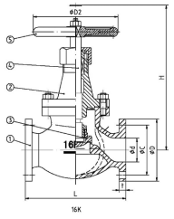
JIS Standard Stop Valve Structure Diagram
Part Name and Material List
| 阀体、阀盖、阀瓣、阀杆Valve Body, Valve Cover, Valve Disc, Valve Stem | 密封面 Sealing Surface | 填料 Packing |
| 铝镍青铜Aluminum Bronze Nickel | 堆焊铁基合金Surfaced Iron-based Alloy 堆焊硬质合金Surfaced Hard Alloy本体材料Base Material四氟乙烯PTFEPolytetrafluoroethylene PTFE铁基合金Iron-based Alloy | 石棉石墨、柔性石墨、聚四氟乙烯Asbestos Graphite, Flexible Graphite, PTFE铁基合金Iron-based Alloy |
Performance Specification Table
| 性能规范表Performance Specification Table | ||
| 公称压力 | 5K/10K/20K | MPa |
| 强度试验压力 | 1.5times | |
| 密封试验压力 | 1.1times | |
| 适用温度 | -196~525 | ℃ |
JIS Standard Stop Valve Dimensional Drawing
JIS Standard Stop Valve Dimensional Table
10K(mm)
| DN | do | L | H | Do | o | t | c | 9 | f | Z×φd | 重量Kg |
| 15 | 13 | 108 | 130 | 100 | 95 | 12 | 70 | 52 | 1 | 4×φ15 | 4 |
| 20 | 19 | 117 | 135 | 120 | 100 | 14 | 75 | 58 | 1 | 4×φ15 | 7.5 |
| 25 | 25 | 127 | 155 | 120 | 125 | 14 | 90 | 70 | 1 | 4×φ19 | 13 |
| 40 | 38 | 165 | 190 | 160 | 140 | 16 | 105 | 85 | 2 | 4×φ19 | 20 |
| 50 | 51 | 203 | 360 | 160 | 155 | 16 | 120 | 100 | 2 | 4×φ19 | 24 |
| 65 | 64 | 216 | 380 | 200 | 175 | 18 | 140 | 120 | 2 | 4×φ19 | 34 |
| 80 | 76 | 241 | 415 | 240 | 185 | 18 | 150 | 130 | 2 | 8×φ19 | 42 |
| 100 | 102 | 292 | 465 | 280 | 210 | 18 | 175 | 155 | 2 | 8×φ19 | 70 |
| 125 | 127 | 356 | 515 | 320 | 250 | 20 | 210 | 185 | 2 | 8×φ23 | 92 |
| 150 | 152 | 406 | 545 | 355 | 280 | 22 | 240 | 215 | 2 | 8×φ23 | 120 |
| 200 | 203 | 495 | 675 | 500 | 330 | 22 | 290 | 265 | 2 | 12×φ23 | 200 |
20K(mm)
| DN | do | L | H | Do | o | t | c | 9 | f | Z×φd | 重量Kg |
| 15 | 13 | 152 | 206 | 120 | 95 | 14 | 70 | 52 | 1 | 4×φ15 | 6 |
| 20 | 19 | 178 | 233 | 140 | 100 | 16 | 75 | 58 | 1 | 4×φ15 | 9 |
| 25 | 25 | 203 | 251 | 160 | 125 | 16 | 90 | 70 | 1 | 4×φ19 | 15 |
| 40 | 38 | 229 | 285 | 200 | 140 | 18 | 105 | 85 | 2 | 4×φ19 | 24 |
| 50 | 51 | 267 | 420 | 240 | 155 | 18 | 120 | 100 | 2 | 8×φ19 | 32 |
| 65 | 64 | 292 | 465 | 280 | 175 | 20 | 140 | 120 | 2 | 8×φ19 | 45 |
| 80 | 76 | 318 | 490 | 320 | 200 | 22 | 160 | 135 | 2 | 8×φ23 | 65 |
| 100 | 102 | 356 | 5906 | 355 | 225 | 24 | 185 | 160 | 2 | 8×φ23 | 100 |
| 125 | 127 | 400 | 90 | 355 | 270 | 26 | 225 | 195 | 2 | 8×φ25 | 120 |
| 200 | 152 | 444 | 760 | 450 | 305 | 28 | 260 | 230 | 2 | 12×φ25 | 190 |
-
 J641W Pneumatic Manual Stop Valve
Model:
J641W-16C/J641W-25C/J641W-40C/J641W-16P/J641W-25P/J641W-40P/J641W-16R/J641W-25R/J641W-40R/Specification:
DN20-DN100Pressure:
PN16~PN40Material:
Cast steel, stainless steel -
 J11T Soviet-style internal thread stop valve
Model:
J11T-10/J11T-16Specification:
DN15~DN50Pressure:
PN10-PN16Material:
Cast iron -
 J64F welded angle type ammonia stop valve
Model:
J64F-25C/J64F-40C/J64F-64C/J64F-160C/J64F-25P/J64F-40P/J64F-64P/J64F-160PSpecification:
DN15-DN125Pressure:
PN25~PN160Material:
Forged steel, forged stainless steel
Address:No. 1, Linxia Road, Sanqiao Industrial Zone, Oubei Sub-district, Yongjia County, Zhejiang Province| Switchboard:0577-67198981| mobile:+8613388552747| Email:sales@shanliuvalve.com|
COPYRIGHT © Zhejiang Shanliu Valve Technology Co., Ltd. Main Business: Water Valve Industrial valve|
浙ICP备2026020749号![]()