Your location:
 /
valves
/
Pressure Reducing Valve
/
Steam Pressure Reducing Valve
/
ZTP Pneumatic Desuperheating and Pressure Reducing Valve
/
valves
/
Pressure Reducing Valve
/
Steam Pressure Reducing Valve
/
ZTP Pneumatic Desuperheating and Pressure Reducing Valve

Mark Classification of Fluid products
- Phone:+86(577)67198981
- Fax:+86(577)67038872
- mobile:+8613388552747
- Sales Email 1:Karrie@shanliuvalve.com
- Sales Email 2:Yannie@shanliuvalve.com
- Sales Email 3:Merry@shanliuvalve.com
- Sales Email 4:Lucas@shanliuvalve.com
- Email:sales@shanliuvalve.com

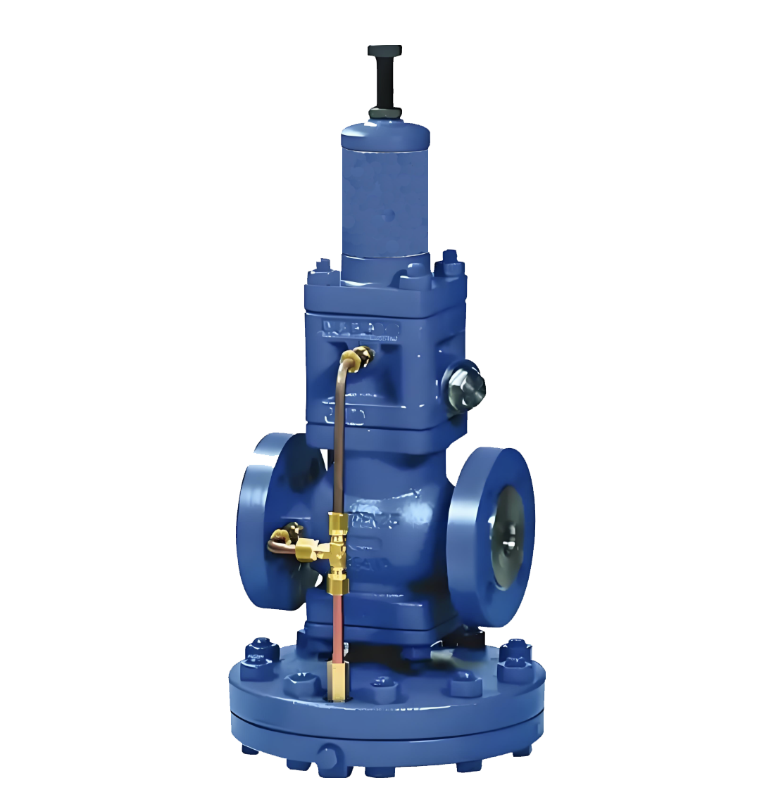
ZTP Pneumatic Desuperheating and Pressure Reducing Valve
- Model:ZTP-16C/ZTP-25C/ZTP-40C/ZTP-64C/ZTP-16P/ZTP-25P/ZTP-40P/ZTP-64P
- Specification:DN50~500
- Temperature: -30~560℃
- Medium:Used for desuperheating and pressure reduction of waste heat in thermal power plants; one valve achieves dual functions
- Pressure:PN1.6~6.4MPa
- Connection method:Flange, Welding
- Driving method:Pneumatic
- Material:Carbon steel, stainless steel


Add QR code to serve you!
- Product Overview
- Performance Data
- Size Weight
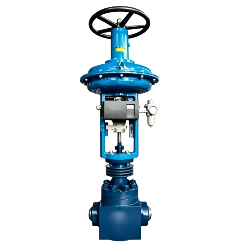
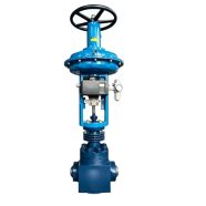
The ZTP pneumatic desuperheating and pressure reducing valve is a high-performance industrial control device that integrates steam pressure regulation and temperature control into a single unit. Specifically designed for waste heat recovery in thermal power plants, boiler steam systems, and various thermal engineering projects, it achieves both pressure reduction and water-spray cooling within a single valve body. The core principle involves a pneumatic actuator driving a multi-stage throttling plug for pressure reduction, combined with a built-in precision atomizing nozzle system that injects desuperheating water uniformly into the high-speed steam flow for rapid heat exchange. The ZTP significantly simplifies pipeline layouts, reduces footprint, and minimizes heat loss. With its exceptional stability under high-temperature and high-pressure-drop conditions, this valve is a core execution element for ensuring the efficient operation of modern thermal networks.
Product Image of ZTP Pneumatic Desuperheating and Pressure Reducing Valve
Feature
1.Dual-function integrated structure:Completes pressure reduction and desuperheating processes simultaneously within one valve body, effectively replacing the traditional combination of a pressure reducing valve and a separate desuperheater, greatly simplifying the process and reducing costs.
2.Multi-stage throttling technology:Internals utilize a multi-stage cage or cascaded structure to release high-pressure steam step-by-step, effectively suppressing flashing and cavitation while significantly reducing noise and vibration caused by high-velocity fluids.
3.Efficient and precise atomization:Features integrated high-performance stainless steel nozzles where water injection is dynamically compensated against steam flow. Precision spray angles ensure complete vaporization within a short distance, offering high temperature control accuracy without the risk of water droplet erosion.
4.Powerful pneumatic drive:Equipped with high-thrust multi-spring diaphragm or piston actuators for stable torque output. Paired with intelligent positioners, it achieves millisecond-level response and precise proportional regulation of process parameters.
5.High-temperature and pressure-resistant materials:Bodies are available in WCB, WC6, WC9, or stainless steel. Sealing surfaces are hard-faced with Stellite to ensure excellent erosion resistance under 560℃ and high-pressure fluctuations.
6.Intrinsic safety and fail-safe protection:Powered by clean compressed air, it provides natural explosion protection. Fail-safe modes (full open or full close) can be configured to ensure the thermal system remains in a safe state during air supply failure.
7.Precision guiding and stability:Utilizes an enhanced cage-guided structure with a large and precise guiding area. This ensures exact axial alignment of the plug throughout its stroke, resisting mechanical stress caused by fluid expansion.
8.Modular maintenance:The compact scientific design features modular internals. Inspection and replacement of the plug, nozzles, and seals can be completed from the top without removing the valve body from the pipeline, shortening downtime.
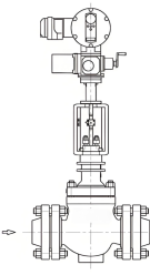
Structural Drawing of ZTP Pneumatic Desuperheating and Pressure Reducing Valve
List of Component Names and Materials
| Item | Material Specification |
| Body Material | NB/T47008, 20, 15CrMo, 12Cr1MoV, A105, A182 F11/F22/F91/F92 |
| Trim Material | A182 F6NM/F11/F22/F91/F92/FXM-19, A479 XM-19, Inconel 718 |
Performance Specification Sheet
| Performance Specification Sheet | |||||
| Nominal Pressure | 1.6 | 2.5 | 4.0 | 6.4 | MPa |
| Strength test pressure | 2.4 | 3.8 | 6.0 | 9.6 | |
| Sealing test pressure | 1.76 | 2.8 | 4.4 | 7.04 | |
| Applicable Temperature | -30~+560 | ℃ | |||
Standard requirements for external dimensions
1. The structural length of the valve shall comply with the standard of GB/T12221
2. Connecting flanges according to GB/T17241.6 standard
Outline dimension table(Unit:mm)
| Nominal Diameter DN | L | L1 | H (1.6-16 MPa) | H1 (1.6-16 MPa) | L2 | H (1.6-16 MPa) | H1 (1.6-16 MPa) | H (1.6-16 MPa High Temp) | H1 (1.6-16 MPa High Temp) | H (1.6-16 MPa) | H1 (1.6-16 MPa) | H (1.6-16 MPa High Temp) | H1 (1.6-16 MPa High Temp) | Desuperheating Water Pipe Diameter CI |
| 50 | 300 | 150 | 520 | 200 | 565 | 800 | 200 | 1030 | 200 | 800 | 260 | 1030 | 260 | 10 |
| 65 | 340 | 170 | 540 | 215 | 650 | 890 | 215 | 1040 | 215 | 890 | 285 | 1040 | 285 | 10 |
| 80 | 380 | 190 | 555 | 225 | 650 | 910 | 225 | 1060 | 225 | 910 | 305 | 1060 | 305 | 20 |
| 100 | 400 | 215 | 580 | 250 | 800 | 950 | 250 | 1100 | 250 | 950 | 330 | 1100 | 330 | 20 |
| 125 | 430 | 225 | 620 | 285 | 800 | 990 | 285 | 1140 | 285 | 990 | 380 | 1140 | 380 | 32 |
| 150 | 450 | 230 | 650 | 330 | 800 | 1090 | 330 | 1240 | 330 | 1090 | 410 | 1240 | 410 | 32 |
| 200 | 500 | 260 | 790 | 355 | 800 | 1160 | 355 | 1310 | 355 | 1160 | 435 | 1310 | 435 | 32 |
| 250 | 550 | 285 | 850 | 390 | 800 | 1230 | 390 | 1380 | 390 | 1230 | 470 | 1380 | 470 | 32 |
| 300 | 750 | 295 | 940 | 480 | 900 | 1370 | 480 | 1570 | 480 | 1370 | 580 | 1570 | 580 | 32 |
| 350 | 850 | 445 | 990 | 550 | 900 | 1450 | 550 | 1650 | 550 | 1450 | 660 | 1650 | 660 | 40 |
| 400 | 950 | 550 | 1120 | 700 | 1000 | 1570 | 700 | 1770 | 700 | 1570 | 800 | 1770 | 800 | 50 |
| 500 | 1130 | 680 | 1660 | 820 | 1000 | 1780 | 820 | 1980 | 820 | - | - | - | - | - |
-
 Y43H Pilot-Operated Steam Pressure Reducing Valve
Model:
Y43H-10C/Y43H-25C/Y43H-40C/Y43H-64C/Y43H-10P/Y43H-25P/Y43H-40P/Y43H-64PSpecification:
DN15-500Pressure:
PN16,PN25,PN40,PN64,PN10Material:
Cast Steel、Stainless Steel -
 Y43H Steam Pressure Reducing Valve (Spirax Sarco Type)
Model:
Y43H-DP27/Y43H-DPE/Y43H-DP27YSpecification:
DN15-DN50Pressure:
PN10,PN21,PN25Material:
Cast Iron, Carbon Steel, Stainless Steel -
 Y945H Electric Steam Pressure Reducing Valve
Model:
Y45H-10C/Y45H-25C/Y45H-40C/Y45H-64C/Y45H-10P/Y45H-25P/Y45H-40P/Y45H-64PSpecification:
DN50-500Pressure:
PN16,PN25,PN40,PN64,PN10Material:
Cast Steel、Stainless Steel

Is the noise from the pressure reducing valve disturbing? Understand the 3 fundamental reasons and solutions in one article
The harsh noise generated by pressure reducing valves during operation is not only an environmental pollution problem, but also a precursor to equipment failure. This article will delve into the three fundamental causes of noise generated by pressure reducing valves - mechanical vibration noise, fluid dynamics noise, and aerodynamic noise, and provide professional solutions.
1、 Mechanical vibration noise: a test of design and process
Mechanical vibration noise is the most common type of noise in pressure reducing valves, mainly divided into two forms:
1. Low frequency vibration noise
Causes:
Medium jet and pressure pulsation
The outlet flow rate of the valve is too fast
Unreasonable pipeline layout
Insufficient rigidity of moving parts inside the valve
2. High frequency vibration noise (resonance phenomenon)
Causes:
The natural frequency of the valve coincides with the excitation frequency of the medium
Easy to occur within a specific decompression range
Sensitive to changes in working conditions, with significant noise fluctuations
Solution:
Optimize the clearance design between the liner and valve stem
Improve machining accuracy
Adjust the natural frequency of the valve
Enhance the rigidity of active components
Select appropriate damping materials
2、 Fluid Dynamics Noise: Challenges in Fluid Control
The turbulence and eddies generated when the fluid passes through the pressure reducing valve can cause significant noise problems.
1. Turbulent noise
Features: Low frequency, low noise level
Cause: Interaction between turbulent fluid and the inner surface of valves/pipelines
Impact: Usually does not constitute a serious noise problem
2. Cavitation noise (the most harmful)
Production mechanism:
During the depressurization process, the fluid flow velocity reaches the critical value
The liquid begins to vaporize, producing bubbles
Bubble explosion under pressure generates shock waves
Local instantaneous pressure can reach 196 MPa
Key data:
Initial value of Δ p: the critical pressure reduction value at which liquid begins to cavitation
Exceeding this value leads to a sharp increase in noise
Preventive measures:
Control the actual pressure reduction value below the critical value
Optimize the design of valve disc fluid direction
Adopting a multi-stage decompression structure
Choose anti cavitation materials
3、 Aerodynamic noise: characteristics of compressible fluids
When compressible fluids such as steam pass through pressure reducing areas, unique noise issues arise:
Production principle:
Conversion of fluid mechanical energy into sound energy
Interaction between high-speed airflow and valve structure
Sudden pressure changes cause gas expansion and sound emission
Control method:
Optimize the design of pressure reducing flow channels
Using mufflers or diffusers
Control the outlet flow rate
Reasonably set back pressure
Comprehensive solutions and selection suggestions
Preventive measures during the design phase
Parameter optimization: Accurately calculate operating parameters to ensure that the pressure reduction value is within the design range
Structural design: Adopting streamlined flow channels to reduce turbulence generation
Material selection: Select special alloys with high rigidity and cavitation resistance
Frequency analysis: avoid the natural frequency of the valve coinciding with the excitation frequency
Key points for installation and maintenance
Correct installation: Ensure the length of the front and rear straight pipe sections to avoid sharp bends
Regular testing: Establish a noise monitoring mechanism to detect problems early on
Timely maintenance: replace worn parts and maintain the best condition of the valve
Brand selection recommendation
High pressure differential operating condition: choose multi-stage pressure reducing valve
Liquid medium: focus on anti cavitation design
Gas/Steam: Focus on Aerodynamic Optimization
Sensitive environment: Choose a low-noise dedicated model
Professional Technical Summary
The essence of the noise problem of pressure reducing valves is the process of energy conversion and release. Fundamentally, all noise issues are closely related to the rationality of valve design, manufacturing process accuracy, and compatibility with operating conditions. Through scientific selection, correct installation, and standardized maintenance, it is entirely possible to control the noise of the pressure reducing valve within an acceptable range.
Immediate action suggestion: If you are troubled by pressure reducing valve noise, it is recommended to first record the noise characteristics (frequency, time period, change pattern), check whether the operating parameters deviate from the design values, and promptly contact professional technicians for diagnosis and treatment.
Keywords of this article: pressure reducing valve noise, mechanical vibration noise, cavitation noise, fluid dynamics noise, pressure reducing valve failure, valve noise reduction, industrial noise control, equipment maintenance
Extended reading: For more professional knowledge about industrial valve selection and maintenance, please follow our technical column to obtain the latest solutions and industry practice cases.
Address:No. 1, Linxia Road, Sanqiao Industrial Zone, Oubei Sub-district, Yongjia County, Zhejiang Province| Switchboard:0577-67198981| mobile:+8613388552747| Email:sales@shanliuvalve.com|
COPYRIGHT © Zhejiang Shanliu Valve Technology Co., Ltd. Main Business: Water Valve Industrial valve|
浙ICP备2026020749号![]()