Your location:
 /
valves
/
More water supply and drainage valves
/
Hydraulic Control Valve
/
500X Diaphragm Pressure Relief/Holding Valve
/
valves
/
More water supply and drainage valves
/
Hydraulic Control Valve
/
500X Diaphragm Pressure Relief/Holding Valve

Mark Classification of Fluid products
- Phone:+86(577)67198981
- Fax:+86(577)67038872
- mobile:+8613388552747
- Sales Email 1:Karrie@shanliuvalve.com
- Sales Email 2:Yannie@shanliuvalve.com
- Sales Email 3:Merry@shanliuvalve.com
- Sales Email 4:Lucas@shanliuvalve.com
- Email:sales@shanliuvalve.com

500X Diaphragm Pressure Relief/Holding Valve
- Model:500X-10/500X-16/500X-25/500X-10P/500X-16P/500X-25P
- Specification:DN50~DN400
- Temperature:≤80℃
- Medium:Water, sewage, seawater, and media similar to water.
- Pressure:PN10~PN25
- Connection method:flange
- Driving method:Spring, automatic
- Material:Cast Iron, Stainless Steel


Add QR code to serve you!
- Product Overview
- Performance Data
- Size Weight
Product Introduction
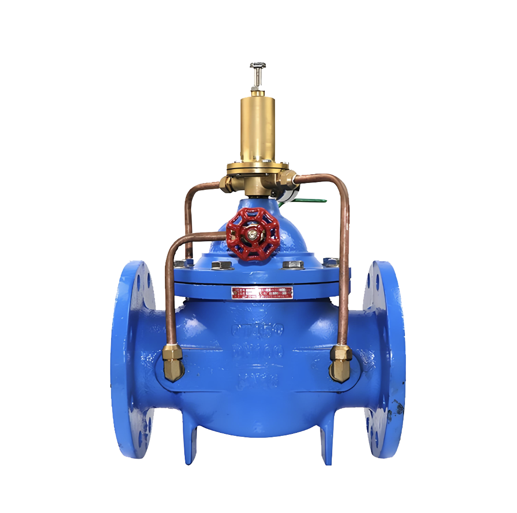
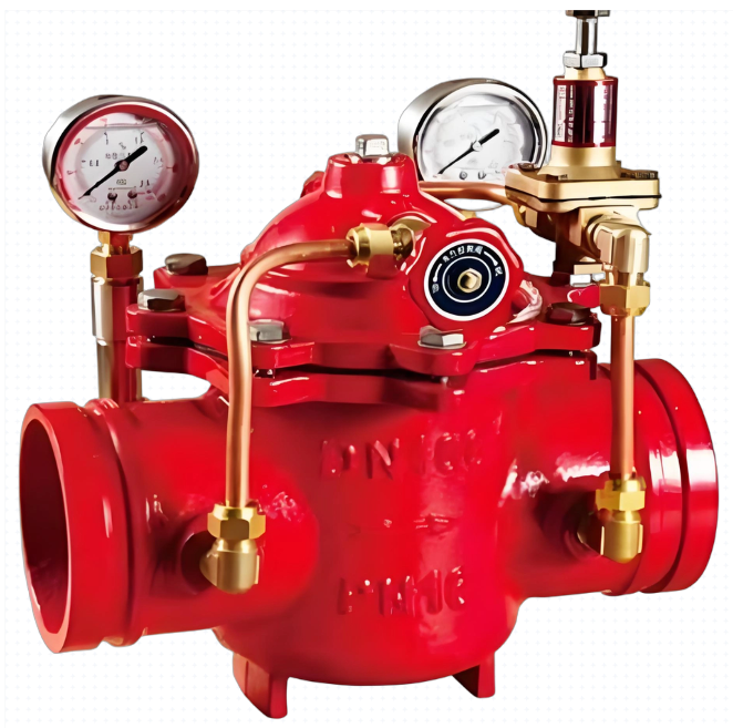
The 500X diaphragm pressure relief/holding valve is a new type of valve developed by our engineering and technical personnel with reference to advanced products of the same type in the United States, France, and China. Hydraulic operation is adopted in the transmission mode and can be automatically controlled, that is, the pressure difference in the control pipeline is used to automatically open and close the main valve, so that the upstream pressure does not exceed a certain set value. The valve body adopts a full channel streamline design, with low fluid resistance, good sealing performance, and sensitive automatic opening and closing performance. The main feature of this valve is that it can be used as both a pressure relief valve and a pressure holding valve. When making a pressure relief valve, it can release the pressure in the water supply pipeline that exceeds the safety setting value of the guide valve, and maintain the pressure in the pipeline below the safety setting value to prevent high pressure or sudden pressure damage to the pipeline or equipment. It can be used for pressure relief in high-rise building fire testing circulation systems and other horizontal systems to prevent system danger caused by high water pressure; When operating a pressure holding valve, the upstream water supply pressure of the main valve can be maintained above a certain set value to ensure the pressure in the upstream water supply area of the main valve. Mainly used in urban low-pressure water supply areas. In short, this product is an ideal choice for water supply systems. Welcome to purchase.

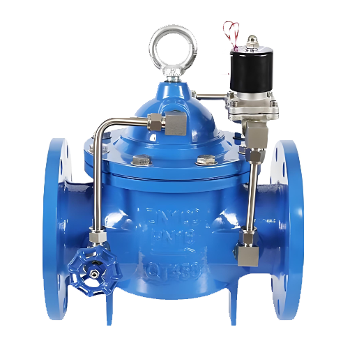
500X diaphragm type pressure relief and holding valve product image
Working principle and purpose
When making a pressure relief valve, the main valve is installed in parallel with the main pipeline in the drainage bypass. When the upstream pressure gradually rises above the set value of pilot valve 13, the main valve quickly opens to release water and reduce pressure until the upstream pressure drops below the set value of pilot valve 13. Only then does the main valve slowly and smoothly close, avoiding water hammer and ensuring the safety of the pipeline. When making a pressure relief valve, it is mainly used to eliminate the gradually increasing high pressure caused by flow supply exceeding demand, such as in the early stage of fire hydrant systems, automatic sprinkler systems, and at the outlet of various water supply systems. When making a pressure relief valve, ball valve 12 is normally open. When making a pressure holding valve, the main valve is installed on the main pipeline, that is, it is installed in series with the main pipeline. As long as the water supply pressure upstream of the main valve is lower than the set value of pilot valve 13, the main valve will be in a closed state. When the water supply pressure upstream of the main valve exceeds the set value of pilot valve 13, the main valve will automatically open and supply water downstream of the main valve, thereby ensuring the water supply pressure upstream of the main valve. Mainly used to maintain the minimum water supply pressure of urban main pipes, especially in case of fire, to prevent excessive pumping and pressure reduction by branch pipe users. When used as a pressure holding valve, ball valve 12 is normally closed or replaced with a plug.
structural form
This valve consists of a main valve, a pilot valve, a needle valve, a ball valve, a pressure gauge, etc. It is divided into diaphragm type and piston type according to different pipe diameters. Due to the pilot valve and needle valve Ball valves and pressure gauges need to be connected to the main valve through conduits, so they are collectively referred to as conduit control systems.
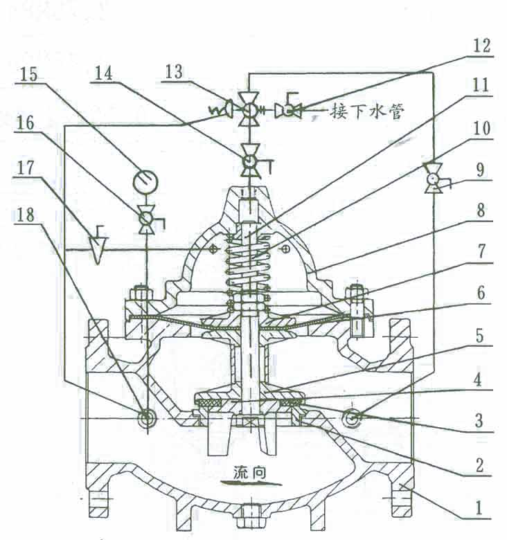
Structure diagram of 500X diaphragm pressure relief and holding valve
Main components and materials
| Serial Number | Part Name | Material | Serial Number | Part Name | Material | |
| 1 | Valve Body | Cast Iron, Stainless Steel | 10 | Compression Spring | Stainless Steel | |
| 2 | Valve Seat | Copper, Stainless Steel | 11 | Valve Stem | Stainless Steel | |
| 3 | Gasket | Reinforced Rubber | 12 | Ball Valve | Copper | |
| 4 | Gasket Pressure Plate | Copper, Stainless Steel | 13 | Pilot Valve | Copper | |
| 5 | Valve Disc | Copper, Stainless Steel | 14 | Ball Valve | Copper | |
| 6 | Diaphragm | Reinforced Rubber | 15 | Pressure Gauge | ||
| 7 | Diaphragm Pressure Plate | Copper, Stainless Steel | 16 | Ball Valve | Copper | |
| 8 | Bonnet | Cast Iron, Stainless Steel | 17 | Needle valve | Copper | |
| 9 | Ball Valve | Bronze | 18 | Microfilter | Stainless Steel |
Main Technical Performance
| Nominal Pressure PN | 1.0MPa | 1.6MPa | 2.5MPa |
| Shell Test Pressure | 1.5MPa | 2.4MPa | 3.75MPa |
| Seal Test Pressure | 1.1MPa | 1.76MPa | 2.75MPa |
| Adjustable Range of Outlet Pressure | 0.09~0.8MPa | 0.10~1.2MPa | 0.15~1.6MPa |
| Applicable Temperature | 0℃~80℃ | ||
| Applicable Medium | Water | ||
Main external installation dimensions
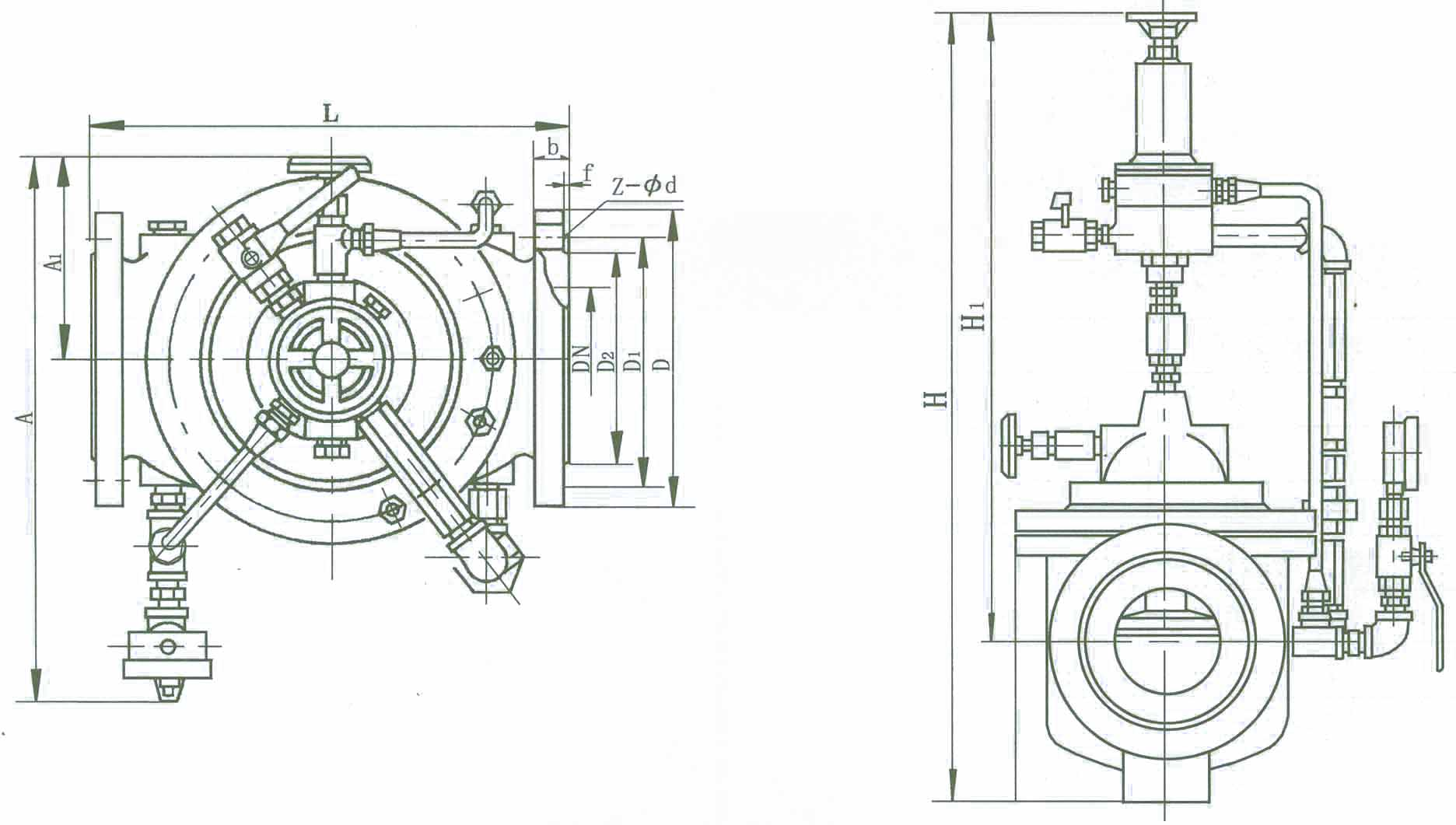
Outline dimension diagram of 500X diaphragm pressure relief and holding valve
Installation dimension diagram of 500X diaphragm pressure relief and holding valve
| DN | Dimensions(mm) | ||||||||||||||||
| L | D | D1 | D2 | Z-фd | A1 | A | H1 | H | |||||||||
| PN10 | PN16 | PN25 | PN10 | PN16 | PN25 | PN10 | PN16 | PN25 | PN10 | PN16 | PN25 | ||||||
| 50 | 240 | 165 | 165 | 165 | 125 | 125 | 125 | 102 | 102 | 99 | 4-ф18 | 4-ф18 | 4-ф18 | 134 | 343 | 516 | 610 |
| 65 | 250 | 185 | 185 | 185 | 145 | 145 | 145 | 122 | 122 | 118 | 4-ф18 | 4-ф18 | 8-ф18 | 141 | 355 | 520 | 625 |
| 80 | 285 | 200 | 200 | 200 | 160 | 160 | 160 | 133 | 133 | 132 | 8-ф18 | 8-ф18 | 8-ф18 | 146 | 360 | 537 | 642 |
| 100 | 360 | 220 | 220 | 235 | 180 | 180 | 190 | 158 | 158 | 156 | 8-ф18 | 8-ф18 | 8-ф22 | 156 | 400 | 596 | 750 |
| 125 | 400 | 250 | 250 | 270 | 210 | 210 | 220 | 184 | 184 | 184 | 8-ф18 | 8-ф18 | 8-ф26 | 170 | 420 | 653 | 808 |
| 150 | 455 | 285 | 285 | 300 | 240 | 240 | 250 | 212 | 212 | 211 | 8-ф22 | 8-ф22 | 8-ф26 | 186 | 435 | 709 | 864 |
| 200 | 585 | 340 | 340 | 360 | 295 | 295 | 310 | 268 | 268 | 274 | 8-ф22 | 12-ф22 | 12-ф26 | 206 | 480 | 805 | 1135 |
| 250 | 650 | 395 | 405 | 425 | 350 | 355 | 370 | 320 | 320 | 330 | 12-ф22 | 12-ф26 | 12-ф30 | 226 | 530 | 855 | 1185 |
| 300 | 800 | 445 | 460 | 485 | 400 | 410 | 430 | 370 | 370 | 389 | 12-ф22 | 12-ф26 | 16-ф30 | 246 | 575 | 953 | 1325 |
| 350 | 860 | 505 | 520 | 555 | 460 | 470 | 490 | 430 | 430 | 448 | 16-ф22 | 16-ф26 | 16-ф33 | 275 | 620 | 990 | 1385 |
| 400 | 960 | 565 | 580 | 620 | 515 | 525 | 550 | 482 | 482 | 503 | 16-ф30 | 16-ф30 | 16-ф36 | 286 | 668 | 1030 | 1445 |
-
 G200X fire pressure reducing valve
Model:
G200X-10/G200X-16/G200X-10Q/G200X-16Q/G200X-10P/G200X-16P/G200X-10T/G200X-16TSpecification:
DN50-DN200Pressure:
PN10~PN16Material:
Cast iron, ductile iron, stainless steel, copper -
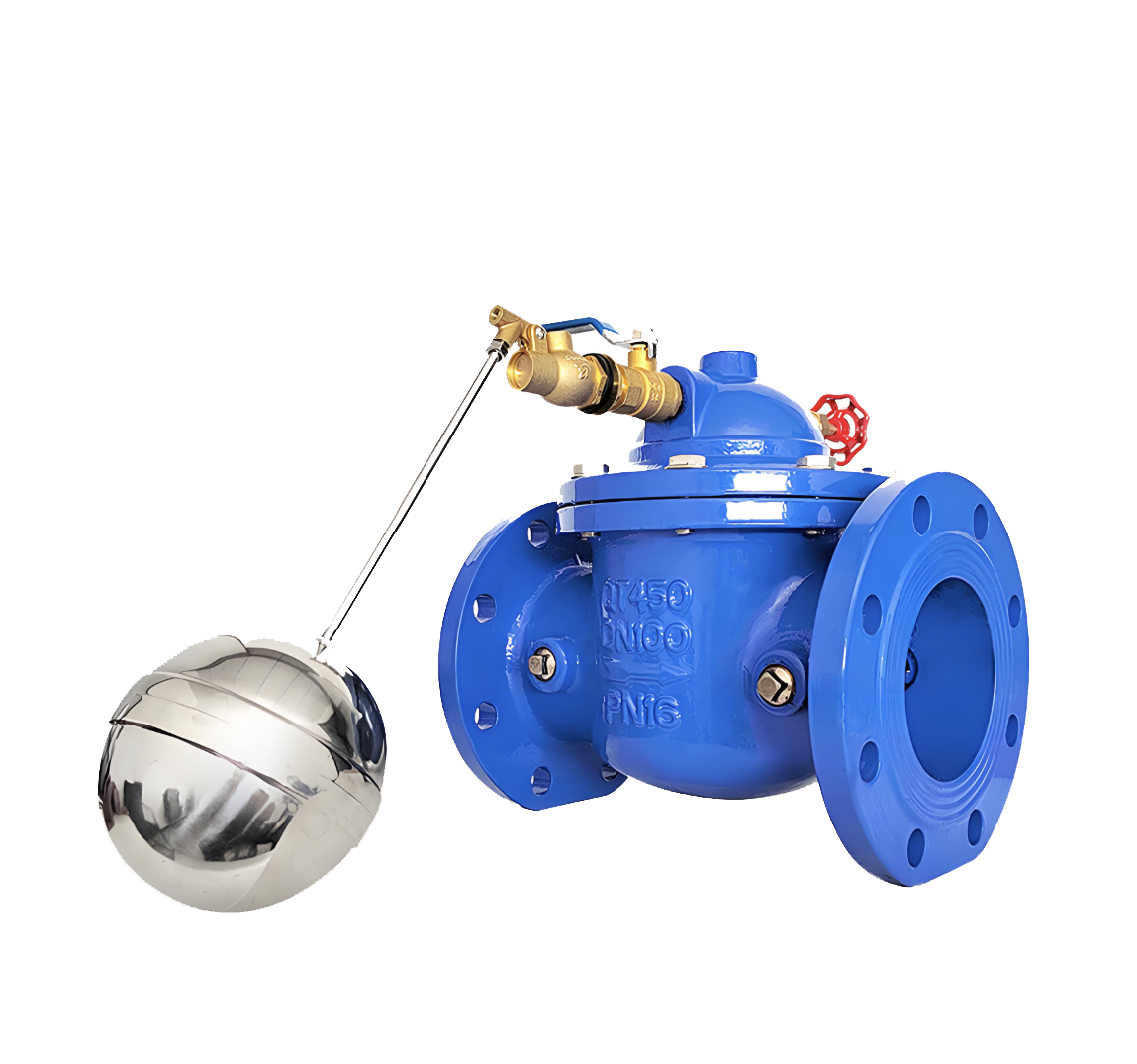 100X Diaphragm Remote Float Valve
Model:
100X-10/100X-16/100X-25/100X-10P/100X-16P/100X-25PSpecification:
DN50~DN400Pressure:
PN10~PN25Material:
Cast iron, stainless steel -
 700X Piston Pump Control Valve
Model:
700X-10/700X-16/700X-25/700X-10P/700X-16P/700X-25PSpecification:
DN350~DN800Pressure:
PN10~PN25Material:
Cast Iron,Ductile Iron,Carbon Steel,Stainless Steel
Address:No. 1, Linxia Road, Sanqiao Industrial Zone, Oubei Sub-district, Yongjia County, Zhejiang Province| Switchboard:0577-67198981| mobile:+8613388552747| Email:sales@shanliuvalve.com|
COPYRIGHT © Zhejiang Shanliu Valve Technology Co., Ltd. Main Business: Water Valve Industrial valve|
浙ICP备2026020749号![]()