Your location:
 /
valves
/
More water supply and drainage valves
/
Mud discharge valve
/
HS742X Stainless Steel Hydraulic Pool Bottom Sludge Discharge Valve
/
valves
/
More water supply and drainage valves
/
Mud discharge valve
/
HS742X Stainless Steel Hydraulic Pool Bottom Sludge Discharge Valve

Mark Classification of Fluid products
- Phone:+86(577)67198981
- Fax:+86(577)67038872
- mobile:+8613388552747
- Sales Email 1:Karrie@shanliuvalve.com
- Sales Email 2:Yannie@shanliuvalve.com
- Sales Email 3:Merry@shanliuvalve.com
- Sales Email 4:Lucas@shanliuvalve.com
- Email:sales@shanliuvalve.com


HS742X Stainless Steel Hydraulic Pool Bottom Sludge Discharge Valve
- Model:HS742P-10P/HS742P-16P/HS742P-25P
- Specification:DN150-DN500
- Temperature:≤450℃
- Medium:Muddy water, Slurry, etc
- Pressure:PN1.0~2.5MPA
- Connection method:flange
- Driving method:Hydraulic
- Material:stainless steel


Add QR code to serve you!
- Product Overview
- Performance Data
- Size Weight
Overview
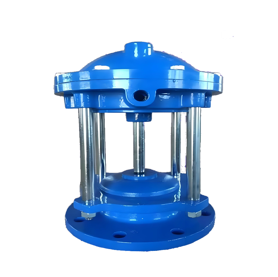
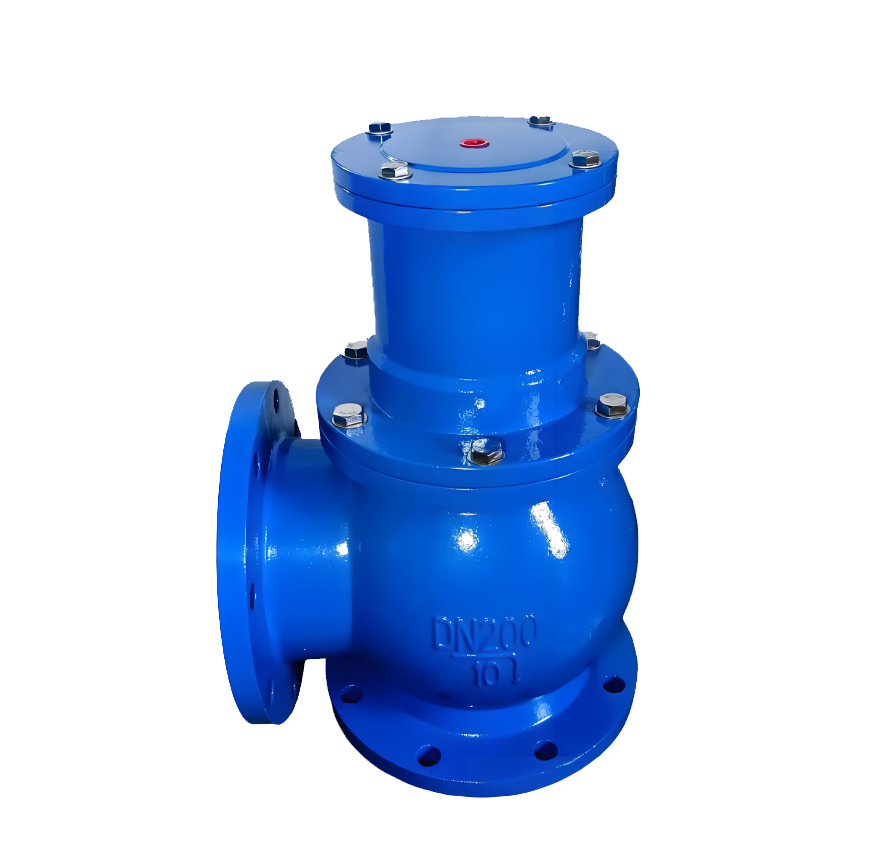
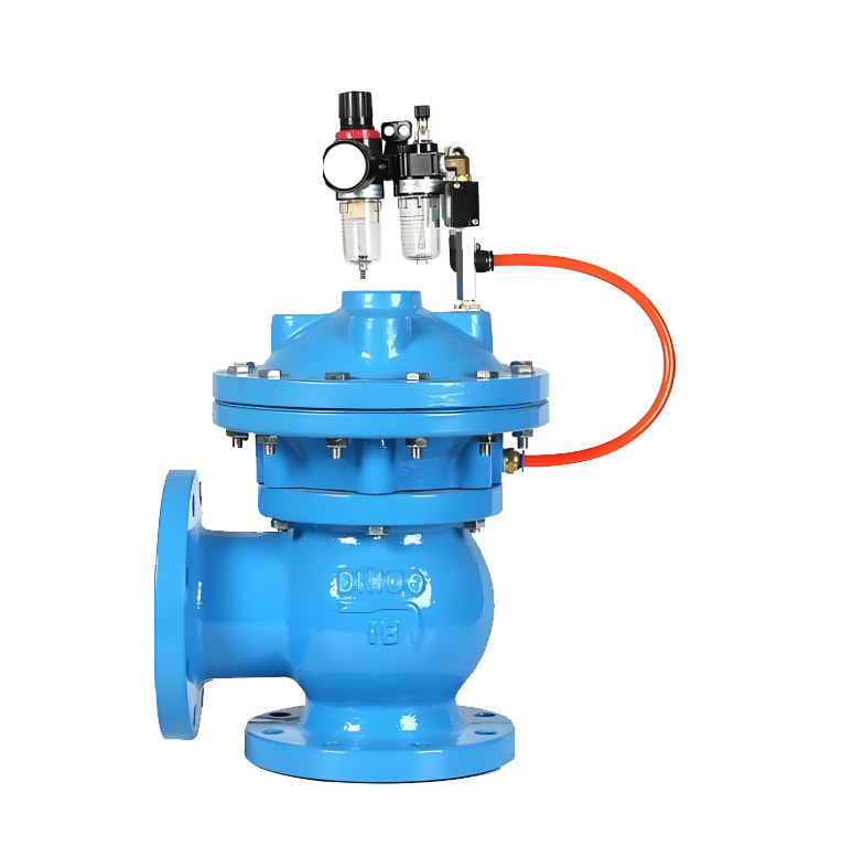
The HS742X Stainless Steel Hydraulic Sludge Discharge Valve is a specialized angular valve designed for sludge discharge in hydraulic systems. Driven by hydraulic cylinders powered by an external hydraulic station, the valve utilizes pressure oil to actuate the piston rod, enabling linear motion that directly operates the connected valve disc for rapid opening and closing. Specifically engineered for sludge discharge in sedimentation tanks, clarifiers, and filtration tanks within water treatment facilities, this valve features stainless steel construction for exceptional corrosion resistance. Its hydraulic drive ensures robust power and stable performance under deep-tank and high-pressure differential conditions, making it a critical component for efficient and reliable automated sludge discharge in large-scale water treatment systems.
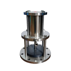
HS742X Stainless Steel Hydraulic Pool Bottom Sludge Discharge Valve Product Diagram
Feature
1. Hydraulic drive delivers high torque and stability: Using hydraulic cylinders as actuators, this system generates substantial linear thrust or pulling force through hydraulic transmission principles, with a driving torque far exceeding pneumatic or electric actuators. This enables valves to effortlessly overcome deep pool water pressure, sludge adhesion forces, and potential jamming, ensuring smooth and reliable operation. It is particularly suitable for demanding industrial environments.
2. The all-stainless-steel construction ensures exceptional corrosion resistance. Key components including the valve body, cover, and disc are fabricated from cast or welded stainless steel (e.g., 304,316). This design enables the valve to withstand common corrosive media in wastewater treatment processes (e.g., chloride-containing water, weak acid/alkali environments), significantly extending its service life in harsh conditions and reducing maintenance requirements.
3. Corner-type pool bottom installation with anti-clogging and sludge discharge: Featuring a corner-shaped structural design, the vertical inlet is directly connected to the sludge discharge short pipe at the pool bottom, while the horizontal or inclined outlet facilitates sludge discharge. This configuration induces a sharp fluid direction change, effectively preventing large debris from clogging the valve chamber and ensuring unobstructed sludge discharge channels.
4. Rigid Sealing and Longevity Design: The valve disc and seat typically employ metal rigid sealing or wear-resistant elastic sealing rings. Coupled with the hydraulic cylinder's powerful closing force, this achieves bidirectional airtight sealing to effectively prevent leakage. The hydraulic system is completely isolated from the medium, resulting in minimal wear on moving parts and extended overall service life.
5. Centralized Control and Automation Integration: The central hydraulic station enables unified operation of multiple valves, facilitating centralized control and power management. Valve status (open, closed, or fault) is easily monitored via oil pressure or limit switches, seamlessly integrating into the plant-wide automation network. This ensures precise timed and sequenced sludge discharge.
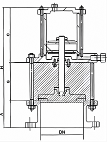
HS742X Stainless Steel Hydraulic Pool Bottom Sludge Discharge Valve Structure Diagram
List of Component Names and Materials
| S/N | Description | Material | Material |
| 1 | Valve Body | CF8 | CF8M |
| 2 | Bonnet | CF8 | CF8M |
| 3 | Diaphragm | NBR | NBR |
| 4 | Disc | WCB+NBR | WCB+NBR |
| 5 | Stem | 304 | 316 |
| 6 | Upper Diaphragm Chamber | CF8 | CF8M |
| 7 | Lower Diaphragm Chamber | CF8 | CF8M |
Performance Specification Sheet
| Performance Specification Sheet | ||||
| Nominal Pressure | 1.0 | 1.6 | 2.5 | MPa |
| Strength test pressure | 1.5 | 2.4 | 3.8 | |
| Sealing test pressure | 1.1 | 1.76 | 2.8 | |
| Applicable Temperature | ≤450 | ℃ | ||
Standard requirements for external dimensions
1. The structural length of the valve shall comply with the standard of GB/T12221
2. Connecting flanges according to GB/T17241.6 standard
HS742X Stainless Steel Hydraulic Pool Bottom Sludge Discharge Valve Outline Diagram
Outline Dimension Table
| Nominal diameter | Key dimension | |||||
| H | S | D | D1 | z-φd | Connection Thread G | |
| 150 | 110 | 490 | 280 | 240 | 8-23 | 1/2" |
| 200 | 110 | 530 | 335 | 295 | 8-23 | 1/2" |
| 250 | 110 | 570 | 390 | 350 | 12-23 | 1/2" |
| 300 | 140 | 610 | 440 | 400 | 12-23 | 3/4" |
| 400 | 140 | 710 | 565 | 515 | 16-25 | 1" |
| 500 | 160 | 310 | 670 | 620 | 20-25 | 1" |
-
 JM742X Diaphragm Type Bottom Sludge Discharge Valve
Model:
JM742X-10/JM742X-16/JM742X-10Q/JM742X-16Q//JM742X-25QSpecification:
DN100-DN400Pressure:
PN10~PN25Material:
Cast Iron, Ductile Iron -
 JM744X Piston-type Sludge Valve
Model:
JM744X-10/JM744X-16/JM744X-10Q/JM744X-16Q/JM744X-25Q/JM744X-10P/JM744X-16P/JM744X-25PSpecification:
DN80-DN400Pressure:
PN10~PN25Material:
Cast Iron, Ductile Iron, Stainless Steel -
 JM644X Pneumatic Sludge Valve
Model:
JM644-10/JM644-16/JM644-10Q/JM644-16Q/JM644-25QSpecification:
DN100-DN400Pressure:
PN10~PN25Material:
Cast Iron, Ductile Iron
Address:No. 1, Linxia Road, Sanqiao Industrial Zone, Oubei Sub-district, Yongjia County, Zhejiang Province| Switchboard:0577-67198981| mobile:+8613388552747| Email:sales@shanliuvalve.com|
COPYRIGHT © Zhejiang Shanliu Valve Technology Co., Ltd. Main Business: Water Valve Industrial valve|
浙ICP备2026020749号![]()