Your location:
 /
valves
/
More water supply and drainage valves
/
Balancing Valve
/
ZLF Self Operated Balancing Valve
/
valves
/
More water supply and drainage valves
/
Balancing Valve
/
ZLF Self Operated Balancing Valve

Mark Classification of Fluid products
- Phone:+86(577)67198981
- Fax:+86(577)67038872
- mobile:+8613388552747
- Sales Email 1:Karrie@shanliuvalve.com
- Sales Email 2:Yannie@shanliuvalve.com
- Sales Email 3:Merry@shanliuvalve.com
- Sales Email 4:Lucas@shanliuvalve.com
- Email:sales@shanliuvalve.com

ZLF Self Operated Balancing Valve
- Model:ZLF-10/ZLF-16/ZLF-10Q/ZLF-16Q/ZLF-25Q/ZLF-10P/ZLF-16P/ZLF-25P
- Specification:DN15-DN350
- Temperature:≤80℃
- Medium:Water and similar media
- Pressure:PN10-PN25
- Connection method:flange
- Driving method: Automatic
- Material:cast iron, ductile iron, stainless steel


Add QR code to serve you!
- Product Overview
- Performance Data
- Size Weight
Overview
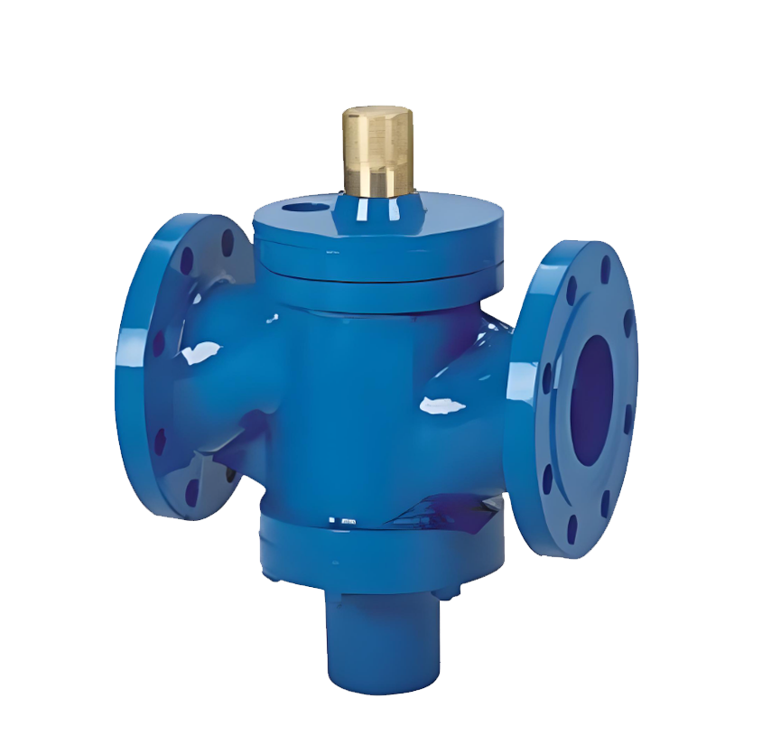
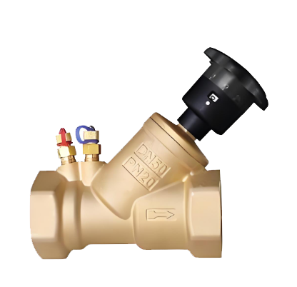
The ZLF self-operated balancing valve is an automatic control valve that operates based on inherent system pressure variations, specifically designed for closed-loop piping systems in HVAC water systems and centralized heating. Equipped with integrated pressure sensing and feedback mechanisms, it dynamically adjusts valve opening in real-time according to pressure differentials or flow rate changes in the controlled loop, thereby maintaining hydraulic parameters (e.g., flow rate or pressure differential) at preset values. Its core function is to dynamically absorb and eliminate excess pressure head in the pipeline network, effectively resolving hydraulic imbalance caused by pressure fluctuations or load variations. This ensures precise flow distribution to terminal devices as needed, making it a critical self-control device for enhancing system stability and energy efficiency.
ZLF Self Operated Balancing Valve Product Diagram
Feature
1. Self-powered without external energy: The valve operates entirely on the pressure differential of the controlled system's medium, eliminating the need for external power, gas, or complex control circuits. This achieves energy-free automated operation with high system reliability and low initial investment and maintenance costs.
2. Precise preset and automatic pressure stabilization: Set and lock the target control value (flow rate or pressure differential) precisely using the adjustment handwheel on the valve top or a dedicated tool. Once set, the valve automatically maintains this parameter within the preset operating range, ensuring rapid response and high accuracy.
3. Extensive operational scope and excellent adaptability: The valve design features a wide adjustable ratio and suitable pressure differential range, capable of meeting dynamic variation requirements under different seasons and operating conditions, ensuring effective performance under all circumstances.
4. Integrated measurement and shut-off function: Most valve models feature standard measurement connectors on the valve body, enabling seamless connection with smart instruments for non-intrusive parameter monitoring, thereby simplifying debugging and diagnostics. Additionally, the valves provide reliable shut-off sealing performance, making them suitable as isolation valves in their respective circuits.
5. Energy efficiency and simplified commissioning: By automatically limiting and stabilizing flow or pressure differentials in each loop, the system significantly reduces the pump's ineffective head and overall energy consumption. Its "post-set automatic operation" feature also greatly reduces the workload for initial system adjustment and subsequent maintenance.
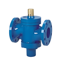
ZLF Self Operated Balancing Valve Structure Diagram
List of Component Names and Materials
| No. | Name | Material |
| 1 | Valve Body, Bonnet | Cast Iron, Ductile Iron, Stainless Steel |
| 2 | Valve Stem | Stainless Steel |
| 3 | Disc | Cast Copper |
| 4 | Diaphragm | Nitrile Rubber (NBR) |
Performance Specification Sheet
| Performance Specification Sheet | ||||
| Nominal Pressure | 1.0 | 1.6 | 2.5 | MPa |
| Strength test pressure | 1.5 | 2.4 | 3.8 | |
| Sealing test pressure | 1.1 | 1.76 | 2.8 | |
| Applicable Temperature | ≤80 | ℃ | ||
Standard requirements for external dimensions
1. The structural length of the valve shall comply with the standard of GB/T12221
2. Connecting flanges according to GB/T17241.6 standard
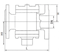
ZLF Self Operated Balancing Valve Outline Diagram
Outline dimension table
| DN(㎜) | L | H | H1 | Flow Control Range ㎡/h |
| 15 | 110 | 72 | 70 | 0.1~1 |
| 20 | 110 | 72 | 70 | 0.1~1.5 |
| 25 | 115 | 81 | 74 | 0.2~2 |
| 32 | 160 | 108 | 91 | 0.5~4 |
| 40 | 200 | 138 | 147 | 1~6 |
| 50 | 215 | 138 | 147 | 2~10 |
| 65 | 230 | 143 | 154 | 3~15 |
| 80 | 275 | 170 | 189 | 5~25 |
| 100 | 290 | 193 | 211 | 10~35 |
| 125 | 310 | 208 | 227 | 15~50 |
| 150 | 350 | 254 | 260 | 30~80 |
| 200 | 430 | 289 | 303 | 40~180 |
| 250 | 520 | 325 | 367 | 100~300 |
| 300 | 635 | 357 | 430 | 150~1500 |
| 350 | 670 | 372 | 495 | 200~7000 |
-
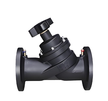 VSHB Static Balancing Valves
Model:
VSHB-10/VSHB-16/VSHB-10Q/VSHB-16Q/VSHB-25Q/VSHB-10P/VSHB-16P/VSHB-25PSpecification:
DN15-DN500Pressure:
PN10~PN25Material:
Cast Iron,Ductile Iron,Stainless Steel -
 SP15F Static Balancing Valve
Model:
SP15F-10T/SP15F-16T/SP15F-25TSpecification:
DN50-DN300Pressure:
PN10~25Material:
Copper -
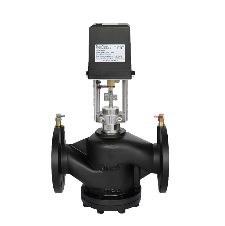 EDRV Electric Dynamic Balance Control Valve
Model:
EDRV41-10/EDRV41-16/EDRV41-10Q/EDRV41-16Q/EDRV41-25Q/EDRV41-10P/EDRV41-16P/EDRV41-25PSpecification:
DN25-DN250Pressure:
PN10~25Material:
Cast Iron, Ductile Iron, Stainless Steel
Address:No. 1, Linxia Road, Sanqiao Industrial Zone, Oubei Sub-district, Yongjia County, Zhejiang Province| Switchboard:0577-67198981| mobile:+8613388552747| Email:sales@shanliuvalve.com|
COPYRIGHT © Zhejiang Shanliu Valve Technology Co., Ltd. Main Business: Water Valve Industrial valve|
浙ICP备2026020749号![]()