Your location:
 /
valves
/
More water supply and drainage valves
/
Balancing Valve
/
VSHB Static Balancing Valves
/
valves
/
More water supply and drainage valves
/
Balancing Valve
/
VSHB Static Balancing Valves

Mark Classification of Fluid products
- Phone:+86(577)67198981
- Fax:+86(577)67038872
- mobile:+8613388552747
- Sales Email 1:Karrie@shanliuvalve.com
- Sales Email 2:Yannie@shanliuvalve.com
- Sales Email 3:Merry@shanliuvalve.com
- Sales Email 4:Lucas@shanliuvalve.com
- Email:sales@shanliuvalve.com

VSHB Static Balancing Valves
- Model:VSHB-10/VSHB-16/VSHB-10Q/VSHB-16Q/VSHB-25Q/VSHB-10P/VSHB-16P/VSHB-25P
- Specification:DN15-DN500
- Temperature:-25~150℃
- Medium:Water and water-like media
- Pressure:PN10~PN25
- Connection method:Flanged, Threaded
- Driving method:Manual
- Material:Cast Iron,Ductile Iron,Stainless Steel


Add QR code to serve you!
- Product Overview
- Performance Data
- Size Weight
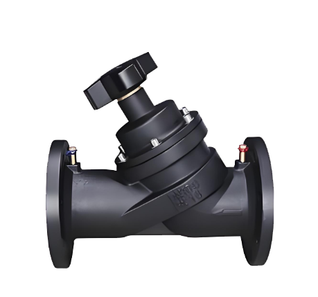
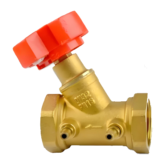
The VSHB static balancing valves are primarily installed in the risers, branch pipes, and terminal units of HVAC systems. Their core function is to accurately preset the maximum flow rate of the pipeline by manually rotating a numeric handwheel in conjunction with a balancing instrument. This process eliminates hydraulic imbalances such as overflow or underflow within the water system, ensuring static hydraulic balance across all branches and enabling the entire HVAC system to operate stably and energy-efficiently.
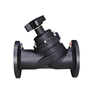
Product Image of VSHB static balancing valves
Feature
1.Pressure-Balanced Plug Design
Feature: The plug adopts a pressure-balanced structure, which significantly offsets the axial thrust exerted by the medium pressure on the plug.
Advantage: Manual adjustment or operation remains effortless and smooth regardless of system pressure, ensuring higher commissioning accuracy.
2.High Flow Coefficient
Feature: Optimized internal flow path design provides a higher Kv value.
Advantage: Minimizes resistance (pressure drop) at the same flow rate, reducing system energy consumption and achieving building energy savings.
3.Precise Numeric Handwheel
Feature: Equipped with a clear digital scale display (typically accurate to 0.1 turns).
Advantage: Operators can intuitively read the current valve opening, facilitating repeatable settings and precise commissioning.
4.Full Shut-off Function
Feature: Beyond its balancing function, the valve provides excellent sealing performance.
Advantage: It can serve as an isolation valve during system maintenance or equipment repair, eliminating the need for additional shut-off valves.
5.Self-sealing Test Ports
Feature: The valve body is equipped with two self-sealing measurement points.
Advantage: Allows rapid connection of differential pressure gauges or flow meters for flow measurement, venting, or draining without leakage upon removal.
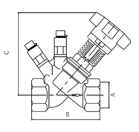
Structural Drawing of VSHB static balancing valves
List of Component Names and Materials
| Component Name | Material |
| Valve Body | Cast Iron, Ductile Iron, Stainless Steel |
| Valve Stem | Stainless Steel |
| Valve Core | Stainless Steel |
| Handwheel | Die-cast Aluminum |
| Valve Body | Brass HPb59-1 |
| Valve Stem | Brass HPb59-1 |
| Valve Core | Brass HPb59-1 |
| Handwheel | PA (Polyamide) |
Performance Specification Sheet
| Performance Specification Sheet | ||||
| Nominal Pressure | 1.0 | 1.6 | 2.5 | MPa |
| Strength test pressure | 1.5 | 2.4 | 3.8 | |
| Sealing test pressure | 1.1 | 1.76 | 2.8 | |
| Applicable Temperature | -25~150 | ℃ | ||
Standard requirements for external dimensions
1. The structural length of the valve shall comply with the standard of GB/T12221
2. Connecting flanges according to GB/T17241.6 standard
3.Threaded Connection: According to GB/T 7306.1.
Outline Drawing of VSHB static balancing valves
Outline dimension table
| Diameter DN | Nominal Pressure PN | Connection Type | Flow Coefficient Kvs (m³/h) | Reference Weight kg |
| 15 | 25 | Thread | 5.8 | 0.8 |
| 20 | 25 | Thread | 8.0 | 0.9 |
| 25 | 25 | Thread | 11 | 1.2 |
| 32 | 25 | Thread | 17 | 1.6 |
| 40 | 25 | Thread | 25 | 2.0 |
| 50 | 25 | Thread | 34 | 3.7 |
| 65 | 25 | Flange | 107 | 15 |
| 80 | 25 | Flange | 145 | 21 |
| 100 | 25 | Flange | 259 | 32 |
| 125 | 25 | Flange | 430 | 47 |
| 150 | 25 | Flange | 647 | 67 |
| 200 | 25 | Flange | 1085 | 126 |
| 250 | 25 | Flange | 1630 | 200 |
| 300 | 25 | Flange | 2495 | 330 |
| 350 | 25 | Flange | 3229 | 450 |
| 400 | 25 | Flange | 4850 | 650 |
| 450 | 25 | Flange | 5500 | 900 |
| 500 | 25 | Flange | 6010 | 1150 |
-
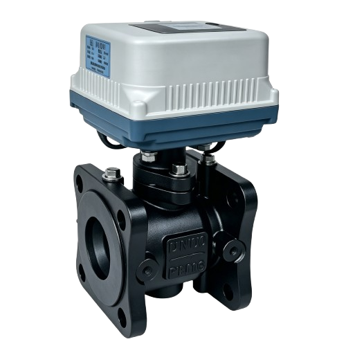
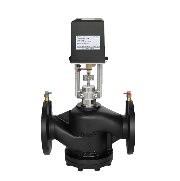 EDRV Electric Dynamic Balance Control Valve
Model:
EDRV41-10/EDRV41-16/EDRV41-10Q/EDRV41-16Q/EDRV41-25Q/EDRV41-10P/EDRV41-16P/EDRV41-25PSpecification:
DN25-DN250Pressure:
PN10~25Material:
Cast Iron, Ductile Iron, Stainless Steel -
 SP15 Brass Female Threaded Static Balancing Valve
Model:
SP15-10T/SP15-16T/SP15-25TSpecification:
DN15-DN40Pressure:
PN10~25Material:
Brass -
 PWQ947F High-Performance Pressure-Balanced Balancing Valve
Model:
PWQ947F-16Q/PWQ947F-16PSpecification:
DN40-DN200Pressure:
PN16Material:
Ductile iron, Stainless steel
Address:No. 1, Linxia Road, Sanqiao Industrial Zone, Oubei Sub-district, Yongjia County, Zhejiang Province| Switchboard:0577-67198981| mobile:+8613388552747| Email:sales@shanliuvalve.com|
COPYRIGHT © Zhejiang Shanliu Valve Technology Co., Ltd. Main Business: Water Valve Industrial valve|
浙ICP备2026020749号![]()