Your location:
 /
valves
/
check valve
/
Swing Check Valve
/
API Check Valve
/
valves
/
check valve
/
Swing Check Valve
/
API Check Valve

Mark Classification of Fluid products
- Phone:+86(577)67198981
- Fax:+86(577)67038872
- mobile:+8613388552747
- Sales Email 1:Karrie@shanliuvalve.com
- Sales Email 2:Yannie@shanliuvalve.com
- Sales Email 3:Merry@shanliuvalve.com
- Sales Email 4:Lucas@shanliuvalve.com
- Email:sales@shanliuvalve.com

API Check Valve
- Model:API
- Specification:2”-32”
- Temperature:≤ 425 ℃
- Medium:Water, Steam, Oil Products, Corrosive Media
- Pressure:150LB,300LB,400LB,600LB,900LB,1500LB
- Connection method:Flange
- Driving method:automated
- Material:WCB、Stainless Steel


Add QR code to serve you!
- Product Overview
- Performance Data
- Size Weight
API Check Valve Overview
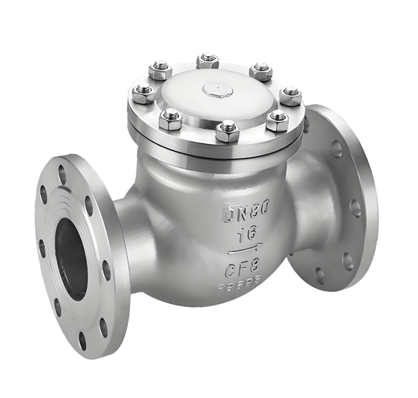
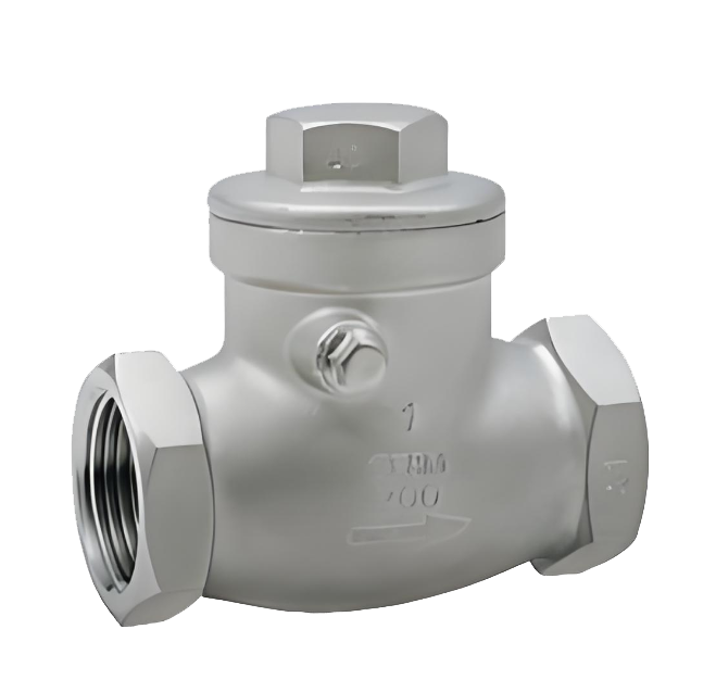
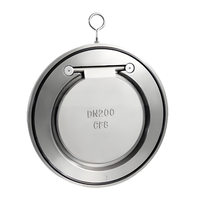
API check valves are automatic valves strictly designed and manufactured in accordance with the American Petroleum Institute (API) standards, primarily used to prevent medium backflow in pipelines. Their core design, materials, manufacturing, and testing comply with specifications such as API 6D. The valve body is typically made of materials like cast steel or stainless steel, with structural types including swing, lift, and dual-plate designs. These valves operate automatically using the kinetic energy of the medium flow, requiring no external intervention. They open under forward flow and close rapidly under reverse flow due to gravity, spring force, or medium pressure. Specifically designed for high-pressure, large-diameter, or safety-critical pipelines in petroleum, natural gas, refining, and chemical industries, API check valves are essential equipment for ensuring unidirectional flow and preventing backflow incidents in industrial systems.
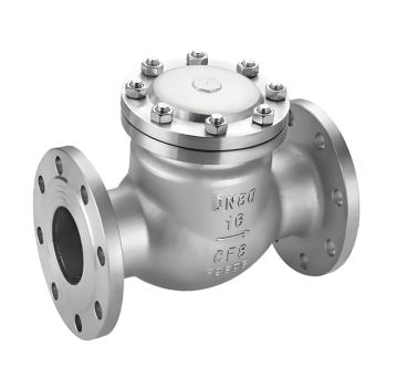
API Check Valve Product Image
API Check Valve Features
1. Strict Compliance with API Standards
The entire process of design, material selection, manufacturing, and testing adheres to API standards, with API 6D certification ensuring high reliability and interchangeability under harsh conditions such as high pressure and corrosion.
2. Reliable Automatic Sealing and Low Flow Resistance
Utilizes precisely matched disc and seat sealing pairs for rapid and tight closure. The unobstructed flow path when open minimizes flow resistance, making it particularly suitable for large-diameter, high-flow-rate transmission pipelines.
3. Diverse Structures for Broad Adaptability
Available in multiple structural designs, including swing, lift, and wafer dual-plate types, to accommodate various installation orientations (horizontal or vertical), medium characteristics (with particles or clean), and pressure fluctuation requirements.
4. Safety Protection and Long Service Life
Features a robust structure that effectively withstands water hammer impacts. Moving parts such as discs and levers are designed for wear and corrosion resistance. Some models are equipped with slow-closing mechanisms to reduce closure impact and extend service life.
5. Easy Maintenance and Wide Applicability
Compact and lightweight designs (e.g., wafer dual-plate type) simplify installation and maintenance. Suitable for water, steam, oil, natural gas, and various corrosive media, with a wide range of operating pressures and temperatures.

API Check Valve Structure Diagram
Parts Name Material List
| 序 号NO. | 名称Name | 材料Material |
| 5 | 阀座seat | 碳钢、不锈钢Carbon Steel, Stainless Steel |
| 4 | 阀瓣disc | 碳钢+STL、不锈钢Carbon Steel+STL, Stainless Steel |
| 3 | 销轴Pin | 2Cr13 |
| 2 | 摇杠Swing Lever | 碳钢、不锈钢Carbon Steel, Stainless Steel |
| 1 | 阀体body | 碳钢、不锈钢Carbon Steel, Stainless Steel |
| 性能规范表Performance Specification | ||
| 公称压力Nominal Pressure | 1.0/1.6/2.5/4/6.4 | Mpa |
| 强度试验压力Shell Test | 1.5/2.4/3.75/6/9.6 | |
| 密封试验压力Seal Test | 1.1/1.76/2.75/4.4/7.04 | |
| 适用温度Suitable Temp. | ≤425 | ℃ |
Dimensions Standard Requirements
1. The structural length of the valve shall conform to the standard ASME16.10.
2. The connecting flange shall conform to the standard ASME16.50.
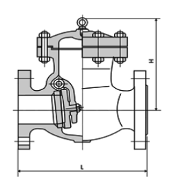
API Check Valve View Drawing
API Check Valve Dimensions Table
| NPS | DN | Class 150Lb | ||||||
| in | mm | L | D | D1 | D2 | b | Z-Φd | H |
| 2" | 50 | 203 | 157 | 120.7 | 92 | 19.50 | 4-Φ19 | 161 |
| 21/2" | 65 | 216 | 178 | 139.7 | 105 | 22.5 | 4-Φ19 | 180 |
| 3" | 80 | 241 | 190.5 | 152.4 | 127 | 24 | 4-Φ19 | 190 |
| 4" | 100 | 292 | 229 | 190.50 | 157.2 | 24 | 8-Φ19 | 220 |
| 6" | 150 | 356 | 279 | 241.5 | 216 | 25.5 | 8-Φ22.5 | 257 |
| 8" | 200 | 495 | 343 | 298.5 | 270 | 29 | 8-Φ22.5 | 292 |
| 10" | 250 | 622 | 406 | 362 | 324 | 30.5 | 12-Φ25 | 350 |
| 12" | 300 | 698 | 483 | 432 | 381 | 32 | 12-Φ25 | 398 |
| 14" | 350 | 787 | 533 | 476.8 | 413 | 35 | 12-Φ29 | 445 |
| 16" | 400 | 864 | 597 | 539.8 | 470 | 37 | 16-Φ29 | 490 |
| 18" | 450 | 978 | 635 | 577.8 | 533 | 40 | 16-Φ32 | 520 |
| 20" | 500 | 978 | 698 | 635 | 584 | 43 | 20-Φ32 | 546 |
| 24" | 600 | 1295 | 813 | 749.3 | 692 | 48 | 20-Φ35 | 880 |
| NPS | DN | Class 300Lb | ||||||
| in | mm | L | D | D1 | D2 | b | Z-Φd | H |
| 2" | 50 | 267 | 165 | 127 | 92 | 22.5 | 8-Φ19 | 179.5 |
| 21/2" | 65 | 292 | 190 | 150 | 105 | 25 | 8-Φ22 | 190 |
| 3" | 80 | 318 | 210 | 168 | 127 | 29.0 | 8-Φ22.5 | 212.4 |
| 4" | 100 | 356 | 254 | 200 | 157 | 32.0 | 8-Φ22.5 | 246 |
| 6" | 150 | 445 | 317.5 | 269.7 | 216 | 37.0 | 12-Φ22.5 | 292 |
| 8" | 200 | 533 | 381 | 330 | 270 | 41.5 | 12-Φ25.5 | 328 |
| 10" | 250 | 622 | 444.5 | 387 | 324 | 48.0 | 16-Φ28.5 | 378.6 |
| 12" | 300 | 711 | 521 | 451 | 381 | 51.0 | 16-Φ32 | 420 |
| 14" | 350 | 838 | 584 | 514 | 54 | 54 | 20-Φ32 | 470 |
| 16" | 400 | 864 | 648 | 572 | 57 | 57 | 20-Φ35 | 530 |
| 18" | 450 | 978 | 711 | 629 | 60 | 60 | 24-Φ35 | 584 |
| 20" | 500 | 1016 | 775 | 686 | 64 | 64 | 24-Φ35 | 610 |
| 24" | 600 | 1346 | 914 | 813 | 70 | 70 | 24-Φ41 | 860 |
| NPS | DN | Class 600Lb | ||||||
| in | mm | L | D | D1 | D2 | b | Z-Φd | H |
| 2" | 50 | 292 | 165 | 127 | 92 | 25 | 8-Φ19 | 203 |
| 21/2" | 65 | 330 | 190 | 150 | 105 | 29 | 8-Φ22 | 229 |
| 3" | 80 | 356 | 210 | 168 | 127 | 32 | 8-Φ22 | 235 |
| 4" | 100 | 432 | 273 | 216 | 157 | 38 | 8-Φ25 | 286 |
| 6" | 150 | 559 | 356 | 292 | 216 | 48 | 8-Φ29 | 330 |
| 8" | 200 | 660 | 419 | 349 | 270 | 56 | 12-Φ29 | 381 |
| 10" | 250 | 787 | 508 | 432 | 324 | 64 | 12-Φ32 | 457 |
| 12" | 300 | 838 | 559 | 489 | 381 | 67 | 16-Φ35 | 584 |
| 14" | 350 | 889 | 603 | 527 | 413 | 70 | 20-Φ38 | 635 |
| 16" | 400 | 991 | 686 | 603 | 470 | 76 | 20-Φ41 | 684 |
-
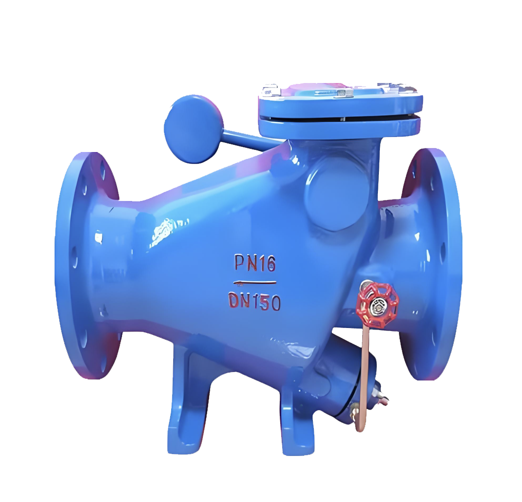 HH44X Heavy Hammer Low-Resistance Slow-Closing Check Valve
Model:
HH44X-10C/HH44X-16C/HH44X-10/HH44X-16/HH44X-10Q/HH44X-16Q/HH44X-10P/HH44X-16PSpecification:
DN40-DN900Pressure:
PN10,PN16Material:
Cast iron, ductile iron -
 H14W Internal Thread Swing Check Valve
Model:
H14W-16PSpecification:
DN15-50Pressure:
PN16Material:
Stainless steel -
 H74H Wafer Swing Check Valve
Model:
H74H-10C/H74H-16C/H74H-25C/H74H-40C/H74H-16P/H74H-25P/H74H-40PSpecification:
DN50-600Pressure:
PN10,PN16,PN25,PN40Material:
Carbon Steel, Stainless Steel

Complete Guide to Check Valve Selection and Installation: Detailed Explanation of Principles, Selection, and Key Construction Points Check valves, as crucial safety components in pipeline systems, are essential for preventing medium backflow and ensuring safe system operation. This article will provide you with a comprehensive guide to the selection and installation of check valves.
1. Operating Principle and Classification of Check Valves 1.1 What is a Check Valve?
Check valves, also known as one-way valves or non-return valves, belong to the category of automatic valves. Their working principle is to achieve opening and closing through the flow force of the medium itself. Their core function is to prevent the reverse flow of pipeline medium and ensure one-way flow.
1.2 Main application scenario: foot valve (a special type of check valve) at the water pump suction inlet
Various pipeline systems requiring unidirectional flow of medium
Industrial settings where accidents caused by medium backflow are to be prevented
II. Selection Criteria and Guidelines for Check Valves 2.1 Basic Selection Principles Medium Adaptability: Suitable for clean medium conditions, not recommended for pipelines containing solid particles or high viscosity media.
2.2 Selection of pipeline size (DN) based on pipeline size. Recommended valve types. Applicable pressure range: DN<50mm. Butterfly check valve, vertical lift check valve, diaphragm check valve. Low-pressure environment: 50mm
Advantages: Effectively eliminates the water hammer phenomenon
Limitations: Subject to temperature and pressure constraints, suitable for low-pressure and normal-temperature pipelines
Applicable scenario: Water supply pipelines prone to water hammer
Slow-closing check valve:
Slow-closing swing check valve
Slow-closing butterfly check valve
Applicable scenario: pipeline systems that require minimal or no water hammer impact when shut down
III. Installation specifications and construction requirements for check valves 3.1 Preparatory work before installation Appearance inspection:
Check the valve nameplate information to ensure compliance with the GB 12220 "General Valve Marking" standard
Check the integrity of the valve and confirm that it is undamaged
Pressure test requirements:
If the working pressure exceeds 1.0 MPa or the main pipe shut-off valve is involved, a pressure test must be conducted
Strength test: Nominal pressure × 1.5, duration ≥ 5 minutes, no leakage is considered as qualified
Tightness test: nominal pressure × 1.1, determine the duration according to GB 50243 standard
3.2 Installation location and direction: Strictly follow the design drawings to determine the location, height, and inlet and outlet directions
Flow direction indicator: Ensure that the flow direction of the medium is completely consistent with the direction indicated by the arrow on the valve body
Pipe support:
It is prohibited to let the check valve bear the weight of the pipeline
Large check valves must be equipped with independent support structures
Avoid direct impact of piping pressure on the valve
3.3 Lift check valves are required for specific types of installations:
Vertical flap type: It must be installed on a vertical pipeline
Horizontal flap type: It must be installed on a horizontal pipeline
Swing check valve:
Ensure that the valve disc's rotating shaft is in a horizontal position during installation
Special attention should be paid to the flow direction of the medium during inclined installation
IV. Common Installation Errors and Precautions 4.1 Example of Incorrect Installation: Installing a Vertical Lift Check Valve on a Horizontal Pipe
The valve flow direction is reversed
Large valves have no independent support
Pressure testing was not conducted according to specifications
4.2 The selection and installation location of check valves should be considered during the design phase of the professional advice system
Provide complete operating condition parameters to the supplier during procurement to obtain professional selection advice
For complex systems, it is recommended to consult a professional valve engineer
Conduct regular maintenance and inspection to ensure the check valve operates in normal condition
5. Maintenance points: Regularly check whether the valve can be opened and closed flexibly
Monitor for abnormal sounds, such as water hammer impact
Check the sealing performance to prevent internal leakage
Lubricate the moving parts to ensure normal operation
The correct selection and installation of check valves are crucial for ensuring the safe operation of pipeline systems. Following the selection guidelines and installation specifications provided in this article can prevent various accidents caused by medium backflow, extend the service life of valves, and reduce maintenance costs.
In practical applications, it is recommended to consider specific engineering requirements and medium characteristics, and if necessary, consult professional valve technicians to ensure the optimization of the selection and installation plan.
Address:No. 1, Linxia Road, Sanqiao Industrial Zone, Oubei Sub-district, Yongjia County, Zhejiang Province| Switchboard:0577-67198981| mobile:+8613388552747| Email:sales@shanliuvalve.com|
COPYRIGHT © Zhejiang Shanliu Valve Technology Co., Ltd. Main Business: Water Valve Industrial valve|
浙ICP备2026020749号![]()