Your location:
 /
valves
/
check valve
/
Lift Check Valve
/
H71W Wafer Check Valve
/
valves
/
check valve
/
Lift Check Valve
/
H71W Wafer Check Valve

Mark Classification of Fluid products
- Phone:+86(577)67198981
- Fax:+86(577)67038872
- mobile:+8613388552747
- Sales Email 1:Karrie@shanliuvalve.com
- Sales Email 2:Yannie@shanliuvalve.com
- Sales Email 3:Merry@shanliuvalve.com
- Sales Email 4:Lucas@shanliuvalve.com
- Email:sales@shanliuvalve.com

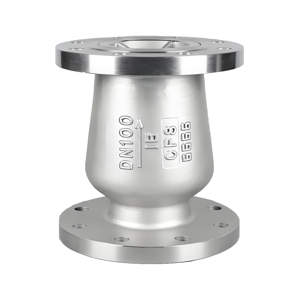
H71W Wafer Check Valve
- Model:H71W-PN40C/H71W-16C/H71W-25C/H71W-16P/H71W-25P/H71W-40P
- Specification: DN15-250
- Temperature:≤ 120 ℃
- Medium:Water and water-like media
- Pressure:PN16,PN25,PN40
- Connection method:Wafer
- Driving method:automated
- Material:Carbon Steel, Stainless Steel


Add QR code to serve you!
- Product Overview
- Performance Data
- Size Weight
H71W Wafer Check Valve Overview
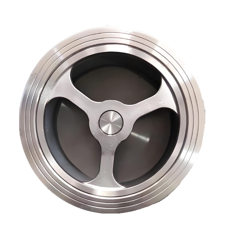
The H71W Wafer Check Valve is a compact and versatile check valve that employs a wafer-type connection. Unlike flanged valves, its body does not incorporate flanges and is instead installed between two pipeline flanges using long bolts. The valve body is typically constructed from materials such as stainless steel, carbon steel, or cast iron, and features an internal single-disc or dual-disc swing-type design.The valve operates by swinging open under forward medium flow and automatically closing under the disc’s own weight, often assisted by a spring, when the medium stops or reverses direction, thereby preventing backflow.Known for its lightweight design, short face-to-face length, and cost-effectiveness, this valve is widely used in space-constrained pipeline systems such as water treatment, HVAC, industrial circulating water, and pump discharge lines. It is suitable for general media including water, oil, and air.
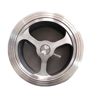
H71W Wafer Check Valve Product Image
H71W Wafer Check Valve Features
1. Compact Structure and Lightweight Design
The wafer-type design eliminates the need for valve body flanges, offering an extremely short face-to-face length and reduced overall weight. This significantly saves installation space and material costs, making it particularly suitable for densely arranged pipelines.
2. Cost-Effective and Easy Installation
The valve is simply clamped between two pipeline flanges using long bolts, enabling quick and straightforward installation without the need for mating flanges. This significantly reduces procurement and installation costs.
3. Low Flow Resistance and Reliable Sealing
The streamlined flow path design minimizes pressure loss. The disc closes rapidly, ensuring reliable sealing to effectively prevent medium backflow. Some models feature a dual-disc design to mitigate water hammer effects.
4. Relatively Simple Maintenance
With a relatively straightforward structure, the valve is easy to disassemble for maintenance or replacement without damaging the pipeline. Some dual-disc designs allow for online inspection and maintenance.
5. Application Scope and Limitations
Suitable for medium to low-pressure conditions (PN10 to PN40) with a typical operating temperature range of -29°C to 150°C. Not recommended for media containing large amounts of solid particles or high viscosity. During installation, ensure pipeline flanges are aligned parallel to each other.
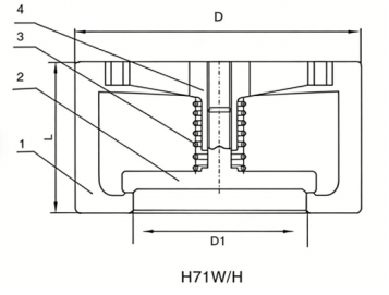
H71W Wafer Check Valve Structure Diagram
Parts Name Material List
| 序 号NO. | 名称Name | 材料Material |
| 4 | 支架shaft | 碳钢、不锈钢Carbon Steel, Stainless Steel |
| 3 | 弹簧spring | 不锈钢Stainless Steel |
| 2 | 阀瓣disc | 碳钢+STL、不锈钢Carbon Steel+STL,Stainless Steel |
| 1 | 阀体body | 碳钢、不锈钢Carbon Steel, Stainless Steel |
| 性能规范表Performance Specification | ||
| 公称压力Nominal Pressure | 1.6/2.5/4 | Mpa |
| 强度试验压力Shell Test | 2.4/3.75/6 | |
| 密封试验压力Seal Test | 1.76/2.75/4.4 | |
| 适用温度Suitable Temp. | ≤120 | ℃ |
Dimensions Standard Requirements
1. The structural length of the valve shall conform to the standard GB/T 12221.
2. The connecting flange shall conform to the standard GB/T 17241.6.
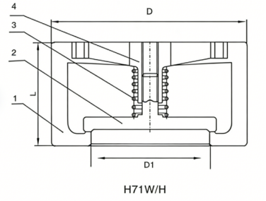
H71W Wafer Check Valve View Drawing
H71W Wafer Check Valve Dimensions Table
| 主要连接尺寸Main connection dimensions | PN16-PN40 | ||||||||||||
| DN | 15 | 20 | 25 | 32 | 40 | 50 | 65 | 80 | 100 | 125 | 150 | 200 | 250 |
| L | 16 | 19 | 22 | 28 | 31.5 | 40 | 46 | 50 | 60 | 90 | 106 | 140 | 160 |
| D | 52 | 62 | 72 | 83 | 93 | 109 | 129 | 144 | 164 | 194 | 220 | 275 | 332 |
| D1 | 15 | 19 | 24 | 31 | 39 | 48 | 63 | 78 | 98 | 123 | 148 | 198 | 248 |
| PN64-PN160 | |||||||||||||
| DN | 15 | 20 | 25 | 32 | 40 | 50 | 65 | 80 | 100 | 125 | 150 | . 200 | . 250 |
| L | 25 | 31.5 | 35.5 | 40 | 45 | 56 | 63 | 71 | 80 | 110 | 125 | 160 | 180 |
| D | 62 | 73 | 83 | 89 | 104 | 114 | 138 | 148 | 174 | 211 | 248 | 310 | 362 |
| D1 | 15 | 19 | 24 | 31 | 39 | 48 | 63 | 78 | 98 | 123 | 148 | 198 | 248 |
-
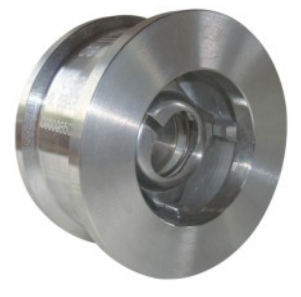
 DRVZ Nozzle Check Valve
Model:
DRVZ-10Q/DRVZ-16Q/DRVZ-25Q/DRVZ-10P/DRVZ-16P/DRVZ-25PSpecification:
DN40~350mmPressure:
PN10~25Material:
Cast iron, ductile iron, stainless steel -
 H71H Wafer-Type Lift Check Valve
Model:
H71H-10C/H71H-16C/H71H-25C/H71H-40C/H71H-10P/H71H-25P/H71H-40PSpecification:
DN15-DN200Pressure:
PN10-PN40Material:
WCB、Stainless Steel -
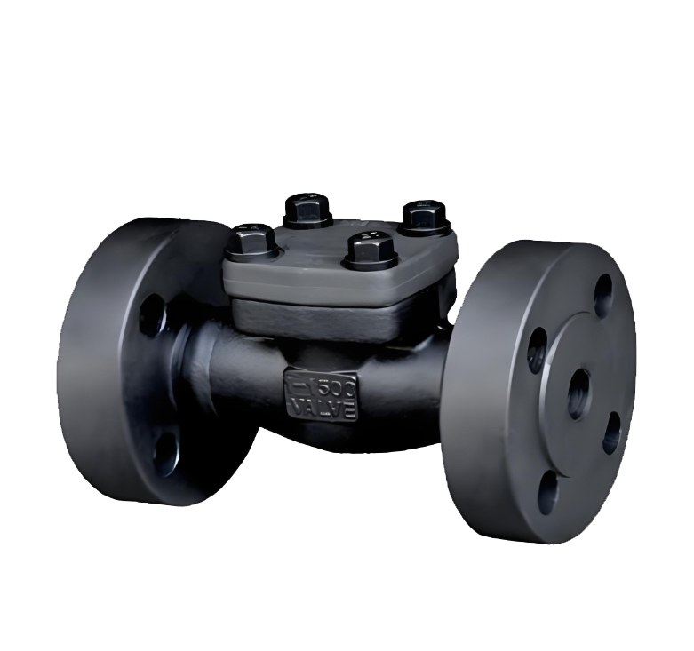 H44H Forged Steel Flange Check Valve
Model:
H44H-16C/H44H-25P/H44H-40P/H44H-40RSpecification:
DN15-50Pressure:
PN16,PN25,PN40Material:
forged steel,forged stainless steel

Complete Guide to Check Valve Selection and Installation: Detailed Explanation of Principles, Selection, and Key Construction Points Check valves, as crucial safety components in pipeline systems, are essential for preventing medium backflow and ensuring safe system operation. This article will provide you with a comprehensive guide to the selection and installation of check valves.
1. Operating Principle and Classification of Check Valves 1.1 What is a Check Valve?
Check valves, also known as one-way valves or non-return valves, belong to the category of automatic valves. Their working principle is to achieve opening and closing through the flow force of the medium itself. Their core function is to prevent the reverse flow of pipeline medium and ensure one-way flow.
1.2 Main application scenario: foot valve (a special type of check valve) at the water pump suction inlet
Various pipeline systems requiring unidirectional flow of medium
Industrial settings where accidents caused by medium backflow are to be prevented
II. Selection Criteria and Guidelines for Check Valves 2.1 Basic Selection Principles Medium Adaptability: Suitable for clean medium conditions, not recommended for pipelines containing solid particles or high viscosity media.
2.2 Selection of pipeline size (DN) based on pipeline size. Recommended valve types. Applicable pressure range: DN<50mm. Butterfly check valve, vertical lift check valve, diaphragm check valve. Low-pressure environment: 50mm
Advantages: Effectively eliminates the water hammer phenomenon
Limitations: Subject to temperature and pressure constraints, suitable for low-pressure and normal-temperature pipelines
Applicable scenario: Water supply pipelines prone to water hammer
Slow-closing check valve:
Slow-closing swing check valve
Slow-closing butterfly check valve
Applicable scenario: pipeline systems that require minimal or no water hammer impact when shut down
III. Installation specifications and construction requirements for check valves 3.1 Preparatory work before installation Appearance inspection:
Check the valve nameplate information to ensure compliance with the GB 12220 "General Valve Marking" standard
Check the integrity of the valve and confirm that it is undamaged
Pressure test requirements:
If the working pressure exceeds 1.0 MPa or the main pipe shut-off valve is involved, a pressure test must be conducted
Strength test: Nominal pressure × 1.5, duration ≥ 5 minutes, no leakage is considered as qualified
Tightness test: nominal pressure × 1.1, determine the duration according to GB 50243 standard
3.2 Installation location and direction: Strictly follow the design drawings to determine the location, height, and inlet and outlet directions
Flow direction indicator: Ensure that the flow direction of the medium is completely consistent with the direction indicated by the arrow on the valve body
Pipe support:
It is prohibited to let the check valve bear the weight of the pipeline
Large check valves must be equipped with independent support structures
Avoid direct impact of piping pressure on the valve
3.3 Lift check valves are required for specific types of installations:
Vertical flap type: It must be installed on a vertical pipeline
Horizontal flap type: It must be installed on a horizontal pipeline
Swing check valve:
Ensure that the valve disc's rotating shaft is in a horizontal position during installation
Special attention should be paid to the flow direction of the medium during inclined installation
IV. Common Installation Errors and Precautions 4.1 Example of Incorrect Installation: Installing a Vertical Lift Check Valve on a Horizontal Pipe
The valve flow direction is reversed
Large valves have no independent support
Pressure testing was not conducted according to specifications
4.2 The selection and installation location of check valves should be considered during the design phase of the professional advice system
Provide complete operating condition parameters to the supplier during procurement to obtain professional selection advice
For complex systems, it is recommended to consult a professional valve engineer
Conduct regular maintenance and inspection to ensure the check valve operates in normal condition
5. Maintenance points: Regularly check whether the valve can be opened and closed flexibly
Monitor for abnormal sounds, such as water hammer impact
Check the sealing performance to prevent internal leakage
Lubricate the moving parts to ensure normal operation
The correct selection and installation of check valves are crucial for ensuring the safe operation of pipeline systems. Following the selection guidelines and installation specifications provided in this article can prevent various accidents caused by medium backflow, extend the service life of valves, and reduce maintenance costs.
In practical applications, it is recommended to consider specific engineering requirements and medium characteristics, and if necessary, consult professional valve technicians to ensure the optimization of the selection and installation plan.
Address:No. 1, Linxia Road, Sanqiao Industrial Zone, Oubei Sub-district, Yongjia County, Zhejiang Province| Switchboard:0577-67198981| mobile:+8613388552747| Email:sales@shanliuvalve.com|
COPYRIGHT © Zhejiang Shanliu Valve Technology Co., Ltd. Main Business: Water Valve Industrial valve|
浙ICP备2026020749号![]()