Your location:
 /
valves
/
industrial valve
/
Cryogenic valve
/
DZ41W Cryogenic Gate Valve
/
valves
/
industrial valve
/
Cryogenic valve
/
DZ41W Cryogenic Gate Valve

Mark Classification of Fluid products
- Phone:+86(577)67198981
- Fax:+86(577)67038872
- mobile:+8613388552747
- Sales Email 1:Karrie@shanliuvalve.com
- Sales Email 2:Yannie@shanliuvalve.com
- Sales Email 3:Merry@shanliuvalve.com
- Sales Email 4:Lucas@shanliuvalve.com
- Email:sales@shanliuvalve.com

DZ41W Cryogenic Gate Valve
- Model:DZ41W-40L/DZ41W-64L/DZ41W-40P/DZ41W-64P
- Specification: 1/2”~36”
- Temperature:-196ºC-~29ºC
- Medium: Combustible gas, Liquefied gas, Liquid oxygen, Liquid nitrogen, Liquefied gases
- Pressure:2Mpa~25Mpa
- Connection method: flange
- Driving method:gear,manual,electric
- Material: Low-temperature steel,Stainless Steel,Duplex stainless steel


Add QR code to serve you!
- Product Overview
- Performance Data
- Size Weight
DZ41W Cryogenic Gate Valve Overview
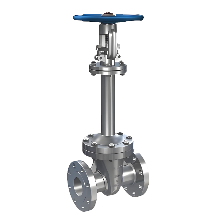
The DZ41W Cryogenic Gate Valve is a high-performance gate valve specifically designed for ultra-low temperature media such as Liquefied Natural Gas (LNG), liquid oxygen, liquid nitrogen, liquid hydrogen, liquid ammonia, and liquid ethylene. It features a flanged connection.The valve body and key components are manufactured from low-temperature resistant stainless steel (such as CF8, F304) or low-temperature alloy steel (such as LCB, LC3). These components undergo deep cryogenic treatment to eliminate residual stresses, ensuring excellent low-temperature toughness and dimensional stability at temperatures as low as -196°C.The gate valve operates by lifting and lowering the gate to open or close, making it suitable for fully open or fully closed shut-off applications. The bonnet length is determined based on the operating temperature, utilizing an extended bonnet design. This positions the stuffing box away from the cold zone, preventing the packing from freezing and mitigating valve stem seizure.This valve is widely used in LNG terminals, air separation units, petrochemical low-temperature installations, and energy systems.
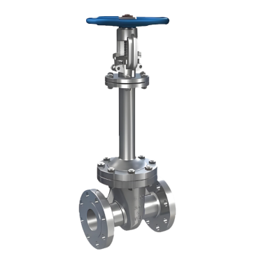
DZ41W Cryogenic Gate Valve Product Image
DZ41W Cryogenic Gate Valve Features
1. Extended Bonnet Anti-Freezing Design: The bonnet length is determined based on the valve's operating temperature, effectively lengthening the path for cold conduction. This ensures the stuffing box remains in a higher temperature zone, preventing the packing from freezing and the valve stem from seizing, guaranteeing flexible and reliable operation.
2. Cryogenic Treatment and Low-Temperature Materials: Key components are manufactured from low-temperature resistant stainless steel or low-temperature alloy steel. The chemical composition and mechanical properties such as low-temperature impact toughness are strictly controlled. Components undergo deep cryogenic treatment to relieve stress, ensuring material stability at -196°C.
3. Cavity Pressure Relief Safety Structure: To prevent abnormal pressure rise in the valve cavity, a pressure relief hole is provided on the inlet side of the gate. This effectively avoids the risk of body damage caused by medium vaporization and expansion, enhancing valve safety.
4. Low Fluid Resistance and Wide Applicability: The medium flow direction is unrestricted, with no flow disturbance or pressure drop, resulting in low fluid resistance and minimal erosion of the sealing surfaces. It is suitable for a wide range of cryogenic media, including methane, ethane, propane, liquid ammonia, liquid oxygen, liquid nitrogen, and liquefied natural gas.
5. Multiple Sealing Surface and Flange Standards: Materials for components such as packing and gaskets (e.g., flexible graphite, PTFE, cryogenic asbestos) are selected based on the operating temperature. Various piping flange standards and sealing face types are available to meet diverse engineering requirements.

DZ41W Cryogenic Gate Valve Structure Diagram
Parts Name Material List
| 序号No. | 名称Name | WCB | CF8 | CF3 | CF3M | CE3MN |
| 1 | 阀体body | A352 LC3 | A351 LF8 | A351 CF3 | A351 CF3M | CE3MN |
| 2 | 阀板disc | A352 LC3 | A351 LF8 | A351 CF3 | A351 CF3M | CE3MN |
| 3 | 阀座seat | A352 LC3 | F304 | F304L | F316L | F53 |
| 4 | 垫片gasket | 304+柔性石墨flexible graphite | 304+柔性石墨flexible graphite | 304+柔性石墨flexible graphite | 304+柔性石墨flexible graphite | 304+柔性石墨flexible graphite |
| 5 | 阀盖bonnet | A352 LC3 | A351 CF8 | A351 CF3 | A351 CF3M | ACE3MN |
| 6 | 上密封座back seat | A182 F304 | F304 | F304L | F316C | F53 |
| 7 | 填料packing | 304+柔性石墨flexible graphite | 304+柔性石墨flexible graphite | 304+柔性石墨flexible graphite | 304+柔性石墨flexible graphite | 304+柔性石墨flexible graphite |
| 性能规范表Performance Specification | ||
| 公称压力Nominal Pressure | 2-25 | Mpa |
| 强度试验压力Shell Test | 3-37.5 | |
| 密封试验压力Seal Test | 2.2-27.5 | |
| 适用温度Suitable Temp. | -29~-196 | ℃ |
Dimensions Standard Requirements
1. The structural length of the valve shall conform to the standard GB/T12221.
2. The connecting flange shall conform to the standard GB/T17241.6.
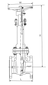
DZ41W Cryogenic Gate Valve View Drawing
DZ41W Cryogenic Gate Valve Dimensions Table
| 2MPA | |||||||||||||||||||
| 规格(NPS) | in | 2 | 21/2 | 3 | 4 | 5 | 6 | 8 | 10 | 12 | 14 | 16 | 18 | 20 | 24 | 28 | 30 | 32 | 36 |
| 结构长度(mm) | L | 178 | 190 | 203 | 229 | 254 | 267 | 292 | 330 | 256 | 381 | 406 | 432 | 457 | 508 | 610 | 610 | 660 | 711 |
| L1 | 191 | 203 | 246 | 241 | 267 | 279 | 305 | 343 | 368 | 394 | 419 | 445 | 470 | 521 | - | ||||
| L2 | 216 | 241 | 283 | 305 | 381 | 403 | 419 | 457 | 502 | 572 | 610 | 660 | 711 | 813 | 914 | 914 | 956 | ||
| 中心高度(mm) | H | 510 | 550 | 590 | 670 | 750 | 800 | 890 | 1150 | 1285 | 1420 | 1550 | 1690 | 1840 | 2140 | 2300 | 2600 | 2830 | 3100 |
| 手轮直径(mm) | W | 200 | 200 | 250 | 280 | 300 | 300 | 350 | 400 | 450 | 500 | 600 | 680 | 750 | 800 | ||||
| 5MPA | |||||||||||||||||||
| 规格(NPS) | in | 2 | 21/2 | 3 | 4 | 5 | 6 | 8 | 10 | 12 | 14 | 16 | 18 | 20 | 24 | 28 | 30 | 32 | 36 |
| 结构长度(mm) | L | 216 | 241 | 283 | 305 | 381 | 403 | 419 | 457 | 502 | 762 | 838 | 914 | 991 | 1143 | 1346 | 1397 | 1524 | 1727 |
| L1 | 232 | 257 | 298 | 321 | 397 | 419 | 435 | 473 | 518 | 778 | 854 | 930 | 1010 | 1165 | 1372 | 1422 | 1553 | 1756 | |
| L2 | 216 | 241 | 283 | 305 | 381 | 403 | 419 | 457 | 502 | 762 | 838 | 914 | 991 | 1143 | 1346 | 1397 | 1524 | 1727 | |
| 中心高度(mm) | H | 515 | 565 | 615 | 690 | 770 | 820 | 915 | 1175 | 1305 | 1450 | 1580 | 1720 | 1860 | 2170 | 2340 | 2640 | 2870 | 3150 |
| 手轮直径(mm) | W | 200 | 200 | 250 | 300 | 300 | 350 | 400 | 450 | 500 | 550 | 680 | 750 | 920 | - | - | - | - | - |
| 10MPA | |||||||||||||||||||
| 规格(NPS) | in | 2 | 21/2 | 3 | 4 | 5 | 6 | 8 | 10 | 12 | 14 | 16 | 18 | 20 | 24 | 28 | 30 | 32 | 36 |
| 结构长度(mm) | L | 292 | 330 | 356 | 432 | 508 | 559 | 660 | 787 | 838 | 889 | 991 | 1092 | 1194 | 1397 | ||||
| L1 | 295 | 333 | 359 | 435 | 511 | 562 | 664 | 791 | 841 | 892 | 994 | 1095 | 1200 | 1407 | |||||
| L2 | 292 | 330 | 356 | 432 | 508 | 559 | 660 | 787 | 838 | 889 | 991 | 1092 | 1194 | 1397 | |||||
| 中心高度(mm) | H | 540 | 595 | 640 | 730 | 810 | 865 | 950 | 1205 | 1345 | 1500 | 1640 | 1760 | 1960 | 2210 | ||||
| 手轮直径(mm) | W | 200 | 250 | 280 | 300 | 400 | 450 | 500 | 680 | 750 | 700 | - | - | - | - | ||||
| 15MPA | |||||||||||||||||||
| 规格(NPS) | in | 2 | 21/2 | 3 | 4 | 5 | 6 | 8 | 10 | 12 | 14 | 16 | 18 | 20 | 24 | ||||
| 结构长度(mm) | L | 368 | 419 | 981 | 457 | 559 | 610 | 737 | 838 | 965 | 1029 | 1130 | |||||||
| L1 | 371 | 422 | 384 | 460 | 562 | 613 | 740 | 841 | 968 | 1039 | 1140 | ||||||||
| L2 | 368 | 419 | 381 | 457 | 559 | 610 | 737 | 838 | 965 | 1029 | 1130 | ||||||||
| 中心高度(mm) | H | 605 | 640 | 700 | 760 | 850 | 905 | 1000 | 1255 | 1400 | 1590 | 1710 | |||||||
| 手轮直径(mm) | W | 300 | 300 | 350 | 400 | - | 600 | 600 | 650 | 700 | - | - | |||||||
| 25MPA | |||||||||||||||||||
| 规格(NPS) | in | 2 | 21/2 | 3 | 4 | 5 | 6 | 8 | 10 | 12 | 14 | 16 | 18 | 20 | 24 | ||||
| 结构长度(mm) | L | 368 | 419 | 470 | 546 | 673 | 705 | 832 | 991 | 1130 | 1257 | 1384 | |||||||
| L1 | 371 | 422 | 473 | 549 | 676 | 711 | 842 | 1001 | 1146 | 1276 | 1406 | ||||||||
| L2 | 368 | 419 | 470 | 546 | 673 | 705 | 832 | 911 | 1130 | 1257 | 1384 | ||||||||
| 中心高度(mm) | H | 625 | 680 | 750 | 800 | 900 | 960 | 1060 | 1300 | 1505 | 1700 | 1800 | |||||||
| 手轮直径(mm) | W | 300 | 350 | 400 | 550 | - | - | - | - | - | - | - |
-
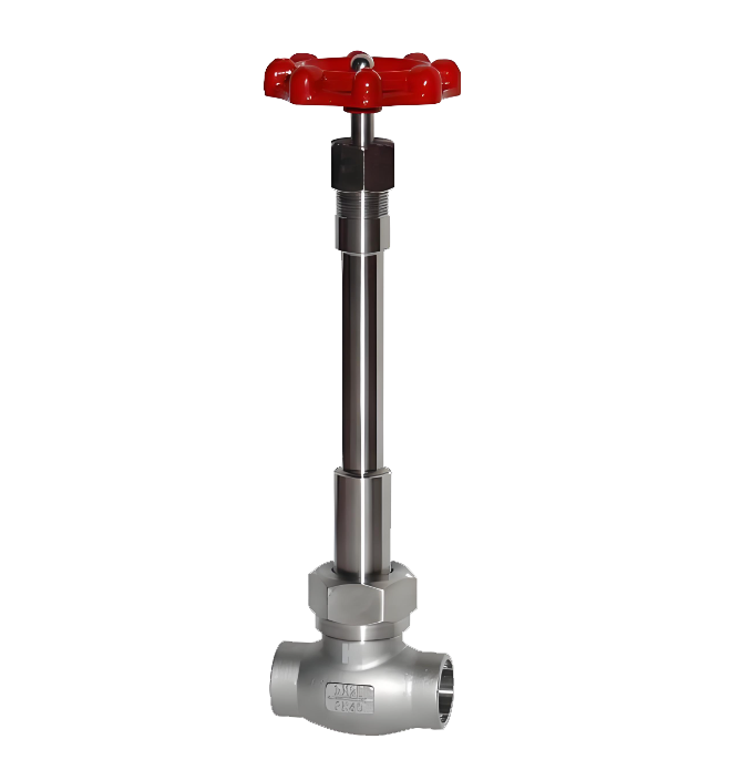 DJ11F Cryogenic Internal Thread Globe Valve
Model:
DJ11F-16P/DJ11F-25P/DJ11F-40P/DJ11F-64P/DJ11F-16R/DJ11F-25R/DJ11F-40R/DJ11F-64R/DJ11F-150LB/DJ11F-300LB/DJ11F-600LB/DJ11F-900LBSpecification:
DN10-DN40Pressure:
PN16~PN64Material:
Stainless Steel, Forged Stainless Steel -
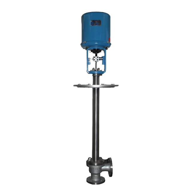 DJ944W Electric Cryogenic Angle Globe Valve
Model:
DJ944W-16P/DJ944W-25P/DJ944W-40P/DJ944W-64P/DJ944W-100PSpecification:
DN100-DN350Pressure:
PN16-PN100Material:
Stainless Steel,Low-temperature steel -
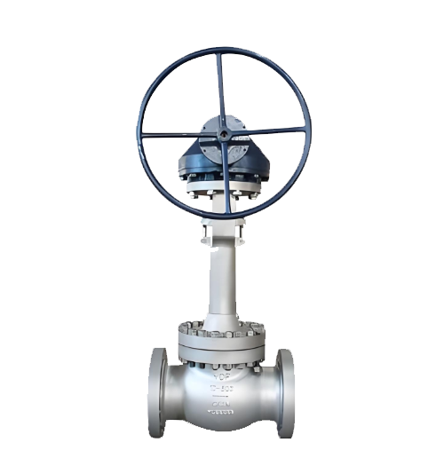 DJ541 Bevel Gear Low Temperature Globe Valve
Model:
DJ541Y-150LB/DJ541Y-300LB/DJ541Y-600LB/DJ541Y-900LB/DJ541Y-1500LB/DJ541Y-2500LBSpecification:
DN50-DN300Pressure:
150LB-2500LBMaterial:
Stainless Steel, Forged Stainless Steel
Address:No. 1, Linxia Road, Sanqiao Industrial Zone, Oubei Sub-district, Yongjia County, Zhejiang Province| Switchboard:0577-67198981| mobile:+8613388552747| Email:sales@shanliuvalve.com|
COPYRIGHT © Zhejiang Shanliu Valve Technology Co., Ltd. Main Business: Water Valve Industrial valve|
浙ICP备2026020749号![]()