Your location:
 /
valves
/
check valve
/
Swing Check Valve
/
H76W Dual Plate Check Valves
/
valves
/
check valve
/
Swing Check Valve
/
H76W Dual Plate Check Valves

Mark Classification of Fluid products
- Phone:+86(577)67198981
- Fax:+86(577)67038872
- mobile:+8613388552747
- Sales Email 1:Karrie@shanliuvalve.com
- Sales Email 2:Yannie@shanliuvalve.com
- Sales Email 3:Merry@shanliuvalve.com
- Sales Email 4:Lucas@shanliuvalve.com
- Email:sales@shanliuvalve.com

H76W Dual Plate Check Valves
- Model:H76W-10C/H76W-16C/H76W-25C/H76W-40C/H76W-64P/H76W-100P/H76W-160P
- Specification:DN50-DN1200
- Temperature:≤ 425 ℃
- Medium:Water, Steam, Oil Products
- Pressure:PN10-PN160
- Connection method:wafer
- Driving method:automated
- Material:WCB、Stainless Steel


Add QR code to serve you!
- Product Overview
- Performance Data
- Size Weight
Overview
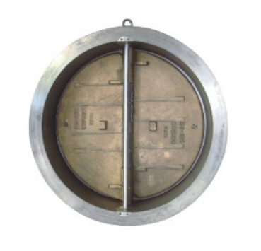
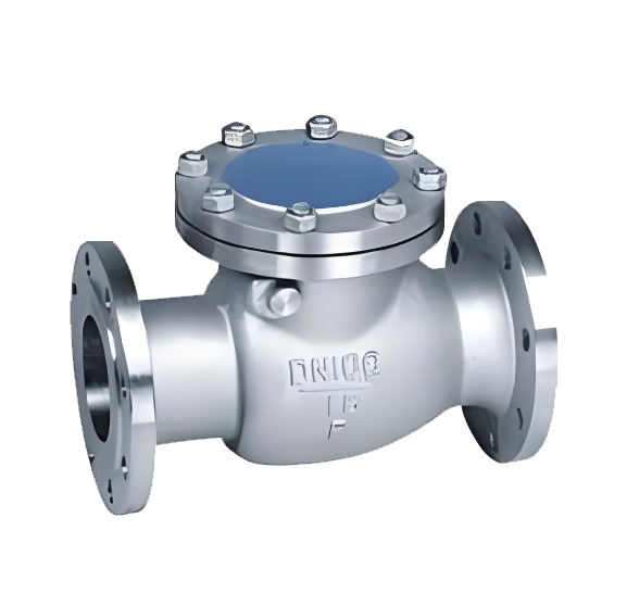
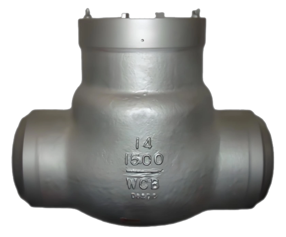
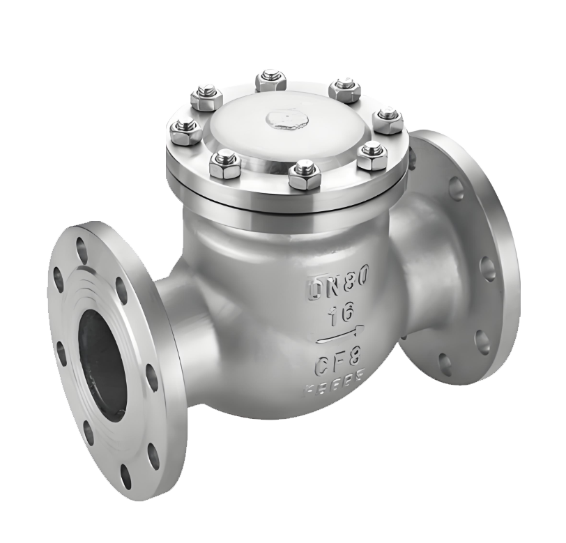
The H76W dual-plate check valve is an energy-efficient check valve that features a twin-disc design and operates automatically based on medium flow. It typically uses a wafer-type connection. The valve body is commonly made of stainless steel, cast steel, or ductile iron, with its two discs performing a symmetrical rotary motion around the same shaft. The valve can be installed either horizontally or vertically. When the medium flows in the forward direction, it pushes the dual discs to open smoothly, and the flow path is nearly straight-through, resulting in low pressure loss. When the medium stops or flows in reverse, the dual discs close rapidly under the combined effect of spring force and reverse medium pressure, ensuring reliable sealing and fast shut-off. This valve is specifically designed for pipeline systems with limited installation space and the need for quick closure. It is widely used in water supply and drainage, fire protection systems, HVAC, and industrial circulating water projects, serving as a compact, economical, and practical pipeline protection device.
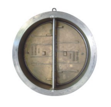
H76W Dual Plate Check Valves Product Image
Features
1.Quick opening and closing due to dual-disc design: The two symmetrical discs rotate around the same shaft, resulting in a short disc stroke and fast closing speed, which effectively reduces water hammer impact. It is especially suitable for pipeline systems with requirements on closing time.
2.Compact structure with wafer connection: The wafer-type connection makes the valve body length only about one-third that of a flanged check valve. It is lightweight, occupies little space, and is easy to install in narrow pipeline locations.
3.Low flow resistance and significant energy saving: The discs open at a large angle, and the flow path is nearly straight-through when fully open, resulting in low fluid resistance and low pressure loss. Long-term operation can effectively reduce pumping energy consumption.
4.Flexible installation and strong adaptability: It can be installed horizontally or vertically (with medium flow from bottom to top). The spring-assisted closing ensures reliable sealing at various installation angles, offering a wide range of applications.
5.Simple maintenance, economical and practical: The structure is simple with a low number of parts, resulting in a low failure rate. The wafer design allows for easy disassembly, facilitating online inspection and maintenance. With high cost-effectiveness, it is widely used in water supply and drainage, fire protection, HVAC, and industrial circulating water systems.
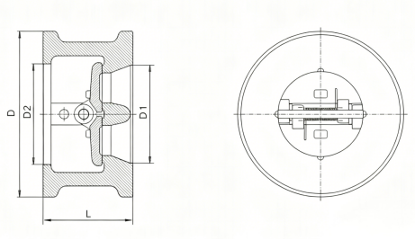
H76W Dual Plate Check Valves Structure Diagram
Parts Name Material List
| 阀体body | 阀瓣disc | 阀座seat | 阀瓣座disc seta | 弹簧spring | 介质接触件Wetted parts |
| A216WCB/A105 | A351 CF8 | 410SS/Stellite | Same as disc | InconelX-750 | 410SS |
| A216 WCB/A105 | A351 CF8 | VITON/BUNA/EPDM | Same as disc | InconelX-750 | 410SS |
| A216WCB/A105 | A351 CF8M | 316SS/Stellite | Same as disc | InconelX-750 | 316SS |
| A216WCB/A105 | A351 CF8M | VITON/BUNA/EPDM | Same as disc | InconelX-750 | 316SS |
| A352LCC/A350 LF2 | A351 CF8M | 316SS/Stellite | Same as disc | InconelX-750 | 316SS |
| A352LCC/A350 LF2 | A351 CF8M | VITON/BUNA/EPDM | Same as disc | InconelX-750 | 316SS |
| A351 CF8M/A182F316 | A351 CF8M | Same as body | Same as disc | InconelX-750 | 316SS |
| A351 CF8M/A182F316 | A351 CF8M | VITON/BUNA/EPDM | Same as disc | InconelX-750 | 316SS |
| A890 GR4A/A182F51 | A890 GR 4A | Same as body | Same as disc | InconelX-750 | A182F51 |
| A890 GR 5A/A182F53 | A890 GR 5A | Same as body | Same as disc | InconelX-750 | A182F53 |
| UNS S31254 | UNS S31254 | Same as body | Same as disc | InconelX-750 | 254-SMO |
| UNS N26625 | UNSN26625 | Same as body | Same as disc | InconelX-750 | Inconel 625 |
| 性能规范表Performance Specification | ||
| 公称压力Nominal Pressure | 1.0-16 | МПа |
| 强度试验压力Shell Test | 1.5-24 | |
| 密封试验压力Seal Test | 1.1-17.6 | |
| 适用温度Suitable Temp. | ≤425 | ℃ |
Dimensions Standard Requirements
1. The structural length of the valve shall conform to the standard ASME16.10.
2. The connecting flange shall conform to the standard ASME16.50.
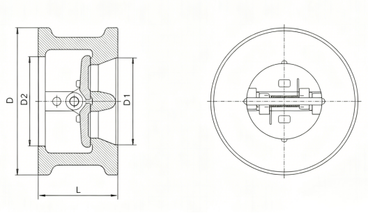
H76W Dual Plate Check Valves View Drawing
H76W Dual Plate Check Valves Dimensions Table
| Pressure Rating | Nominal Size DN | Dimensions | Pipe Flange | Weight (kg) | |||||||
| L | D | D1 | D2 | Diam.of Bolts Circle | No of Bolt holes | Diam.of Bolt holes | Diam.of Bolts | Length of Bolts | |||
| PN10 | 50 | 60 | 108 | 51 | 55 | 125 | 4 | 18 | M16 | 150 | 2.2 |
| 65 | 67 | 128 | 65 | 68 | 145 | 8 | 18 | M16 | 155 | 3.1 | |
| 80 | 73 | 142 | 80 | 82 | 160 | 8 | 18 | M16 | 160 | 4.3 | |
| 100 | 73 | 162 | 102 | 108 | 180 | 8 | 18 | M16 | 165 | 6.3 | |
| 125 | 86 | 192 | 127 | 130 | 210 | B | 18 | M16 | 180 | 8.4 | |
| 150 | 98 | 218 | 152 | 165 | 240 | 8 | 22 | M20 | 205 | 12.6 | |
| 200 | 127 | 273 | 203 | 220 | 295 | 8 | 22 | M20 | 235 | 24 | |
| 250 | 146 | 328 | 254 | 270 | 350 | 12 | 22 | M20 | 255 | 40 | |
| 300 | 181 | 378 | 305 | 320 | 400 | 12 | 22 | M20 | 290 | 66 | |
| 350 | 184 | 438 | 337 | 350 | 460 | 16 | 22 | M20 | 295 | 83 | |
| 400 | 191 | 489 | 387 | 400 | 515 | 16 | 26 | M24 | 310 | 102 | |
| 450 | 203 | 539 | 438 | 438 | 565 | 20 | 26 | M24 | 325 | 124 | |
| 500 | 219 | 594 | 495 | 495 | 620 | 20 | 26 | M24 | 345 | 150 | |
| 600 | 222 | 696 | 595 | 595 | 725 | 20 | 30 | M27 | 355 | 203 | |
| 700 | 305 | 811 | 685 | 685 | 840 | 24 | 30 | M27 | 440 | 380 | |
| 800 | 305 | 918 | 780 | 780 | 950 | 24 | 33 | M30 | 450 | 580 | |
| 900 | 368 | 1018 | 875 | 875 | 1050 | 28 | 33 | M30 | 520 | 665 | |
| 1000 | 432 | 1124 | 975 | 975 | 1160 | 28 | 36 | M33 | 590 | 880 | |
| 1200 | 524 | 1340 | 1165 | 1165 | 1380 | 32 | 39 | M36 | 695 | 1470 | |
| Pressure Rating | Nominal Size DN | Dimensions | Pipe Flange | Weight (kg) | |||||||
| L | D | D1 | D2 | Diam.of Bolts Circle | No of Bolt holes | Diam.of Bolt holes | Diam of Bolts | Length of Bolts | |||
| PN16 | 50 | 60 | 108 | 51 | 55 | 125 | 4 | 18 | M16 | 150 | 2.2 |
| 65 | 67 | 128 | 65 | 68 | 145 | 8 | 18 | M16 | 155 | 3.1 | |
| 80 | 73 | 142 | 80 | 82 | 160 | 8 | 18 | M16 | 160 | 4.3 | |
| 100 | 73 | 162 | 102 | 108 | 180 | 8 | 18 | M16 | 165 | 6.3 | |
| 125 | 86 | 192 | 127 | 130 | 210 | 8 | 18 | M16 | 180 | 8.4 | |
| 150 | 98 | 218 | 152 | 165 | 240 | 8 | 22 | M20 | 205 | 12.6 | |
| 200 | 127 | 273 | 203 | 220 | 295 | 12 | 22 | M20 | 235 | 24 | |
| 250 | 146 | 329 | 254 | 270 | 355 | 12 | 26 | M24 | 265 | 40 | |
| 300 | 181 | 384 | 305 | 320 | 410 | 12 | 26 | M24 | 305 | 66 | |
| 350 | 184 | 444 | 337 | 350 | 470 | 16 | 26 | M24 | 310 | 83 | |
| 400 | 191 | 496 | 387 | 400 | 525 | 16 | 30 | M27 | 330 | 102 | |
| 450 | 203 | 556 | 438 | 438 | 585 | 20 | 30 | M27 | 345 | 124 | |
| 500 | 219 | 618 | 495 | 495 | 650 | 20 | 33 | M30 | 370 | 150 | |
| 600 | 222 | 732 | 595 | 595 | 770 | 20 | 36 | M33 | 380 | 203 | |
| 700 | 305 | 802 | 685 | 685 | 840 | 24 | 36 | M33 | 470 | 380 | |
| 800 | 305 | 912 | 780 | 780 | 950 | 24 | 39 | M36 | 475 | 580 | |
| 900 | 368 | 1012 | 875 | 875 | 1050 | 28 | 39 | M36 | 545 | 665 | |
| 1000 | 432 | 1126 | 975 | 975 | 1170 | 28 | 42 | M39 | 620 | 880 | |
| 1200 | 524 | 1340 | 1165 | 1165 | 1390 | 32 | 48 | M45 | 735 | 1470 | |
| Pressure Rating | Nominal Size DN | Dimensions | Pipe Flange | Weight (kg) | |||||||
| L | D | D1 | D2 | Diam.of Bolts Circle | No.of Bolt holes | Diam.of Bolt holes | Diam.of Bolts | Length of Bolts | |||
| PN25 | 50 | 60 | 108 | 51 | 55 | 125 | 4 | 18 | M16 | 150 | 2.2 |
| 65 | 67 | 128 | 65 | 68 | 145 | 8 | 18 | M16 | 160 | 3.1 | |
| 80 | 73 | 142 | 80 | 82 | 160 | 8 | 18 | M16 | 170 | 4.3 | |
| 100 | 73 | 168 | 102 | 108 | 190 | 8 | 22 | M20 | 180 | 6.3 | |
| 125 | 86 | 194 | 127 | 130 | 220 | 8 | 26 | M24 | 205 | 8.4 | |
| 150 | 98 | 224 | 152 | 165 | 250 | 8 | 26 | M24 | 220 | 13.5 | |
| 200 | 127 | 284 | 203 | 220 | 310 | 12 | 26 | M24 | 255 | 26 | |
| 250 | 146 | 341 | 254 | 270 | 370 | 12 | 30 | M27 | 285 | 43 | |
| 300 | 181 | 401 | 305 | 320 | 430 | 16 | 30 | M27 | 325 | 70 | |
| 350 | 184 | 458 | 337 | 350 | 490 | 16 | 33 | M30 | 340 | 90 | |
| 400 | 191 | 515 | 387 | 400 | 550 | 16 | 36 | M33 | 360 | 110 | |
| 450 | 203 | 565 | 438 | 438 | 600 | 20 | 36 | M33 | 375 | 135 | |
| 500 | 219 | 622 | 495 | 495 | 660 | 20 | 36 | M33 | 395 | 158 | |
| 600 | 222 | 732 | 595 | 595 | 770 | 20 | 39 | M36 | 410 | 220 | |
| 700 | 305 | 831 | 685 | 685 | 875 | 24 | 42 | M39 | 500 | 400 | |
| 800 | 305 | 942 | 780 | 780 | 990 | 24 | 48 | M45 | 520 | 600 | |
| 900 | 368 | 1040 | 875 | 875 | 1090 | 28 | 48 | M45 | 590 | 685 | |
| 1000 | 432 | 1155 | 975 | 975 | 1210 | 28 | 56 | M52 | 675 | 900 | |
| 1200 | 524 | 1365 | 1165 | 1165 | 1420 | 32 | 56 | M52 | 790 | 1510 | |
| Pressure Rating | Nominal Size DN | Dimensions | Pipe Flange | Weight kg) | |||||||
| L | D | D1 | D2 | Diam.of Bolts Circle | No.of Bolt holes | Diam.of Bolt holes | Diam.of Bolts | Length of Bolts | |||
| PN40 | 50 | 60 | 108 | 51 | 55 | 125 | 4 | 18 | M16 | 150 | 2.5 |
| 65 | 67 | 128 | 65 | 68 | 145 | 8 | 18 | M16 | 160 | 4 | |
| 80 | 73 | 142 | 80 | 82 | 160 | 8 | 18 | M16 | 170 | 5 | |
| 100 | 73 | 168 | 102 | 108 | 190 | 8 | 22 | M20 | 180 | 7 | |
| 125 | 86 | 194 | 127 | 130 | 220 | 8 | 26 | M24 | 205 | 11.2 | |
| 150 | 98 | 224 | 152 | 165 | 250 | 8 | 26 | M24 | 220 | 16.5 | |
| 200 | 127 | 291 | 203 | 220 | 320 | 12 | 30 | M27 | 270 | 31.5 | |
| 250 | 146 | 353 | 254 | 270 | 385 | 12 | 33 | M30 | 300 | 49.5 | |
| 300 | 181 | 418 | 305 | 320 | 450 | 16 | 33 | M30 | 345 | 81 | |
| 350 | 222 | 475 | 337 | 343 | 510 | 16 | 36 | M33 | 400 | 117 | |
| 400 | 232 | 547 | 387 | 400 | 585 | 16 | 39 | M36 | 425 | 158 | |
| 450 | 264 | 572 | 438 | 438 | 610 | 20 | 39 | M36 | 470 | 200 | |
| 500 | 292 | 626 | 495 | 495 | 670 | 20 | 42 | M39 | 505 | 285 | |
| 600 | 318 | 745 | 595 | 595 | 795 | 20 | 48 | M45 | 575 | 380 | |
| Pressure Rating | Nominal Size DN | Dimensions | Pipe Flange | Weight (kg) | ||||||||
| L | D | D1 | D2 | Diam.of Bolts Circle | No of Bolt holes | Diam.of Bolt holes | Diam of Bolts | Length of Bolts | ||||
| RF | RTJ | |||||||||||
| PN63 | 50 | 60 | 114 | 51 | 55 | 135 | 4 | 22 | M20 | 170 | 185 | 2.5 |
| 65 | 67 | 138 | 65 | 68 | 160 | 8 | 22 | M20 | 180 | 195 | 4 | |
| 80 | 73 | 148 | 80 | 82 | 170 | 8 | 22 | M20 | 190 | 205 | 5 | |
| 100 | 79 | 174 | 102 | 108 | 200 | 8 | 26 | M24 | 210 | 225 | 9 | |
| 125 | 105 | 211 | 127 | 130 | 240 | 8 | 30 | M27 | 250 | 265 | 14.5 | |
| 150 | 136 | 248 | 152 | 165 | 280 | 8 | 33 | M30 | 290 | 305 | 27 | |
| 200 | 165 | 310 | 200 | 210 | 345 | 12 | 36 | M33 | 335 | 350 | 48 | |
| 250 | 213 | 362 | 250 | 255 | 400 | 12 | 36 | M33 | 395 | 410 | 93.5 | |
| 300 | 229 | 422 | 300 | 300 | 460 | 16 | 36 | M33 | 420 | 435 | 114.5 | |
| 350 | 273 | 487 | 335 | 335 | 525 | 16 | 39 | M36 | 480 | 495 | 187 | |
| 400 | 305 | 541 | 385 | 385 | 585 | 16 | 42 | M39 | 525 | 540 | 261 | |
| Pressure Rating | Nominal Size DN | Dimensions | Pipe Flange | Weight (kg) | ||||||||
| L | D | D1 | D2 | Diam.of Bolts Circle | No of Bot holes | Diam.of Bolt holes | Diam.of Bolts | Length of Bolts | ||||
| RF | RTJ | |||||||||||
| PN100 | 50 | 60 | 120 | 51 | 55 | 145 | 4 | 26 | M24 | 185 | 200 | 2.5 |
| 65 | 67 | 144 | 65 | 68 | 170 | 8 | 26 | M24 | 195 | 210 | 4 | |
| 80 | 73 | 154 | 80 | 82 | 180 | 8 | 26 | M24 | 205 | 220 | 5 | |
| 100 | 79 | 181 | 102 | 108 | 210 | 8 | 30 | M27 | 225 | 240 | 9 | |
| 125 | 105 | 218 | 127 | 130 | 250 | 8 | 33 | M30 | 265 | 280 | 14.5 | |
| 150 | 136 | 258 | 152 | 165 | 290 | 12 | 33 | M30 | 305 | 320 | 27 | |
| 200 | 165 | 324 | 200 | 210 | 360 | 12 | 36 | M33 | 355 | 370 | 48 | |
| 250 | 213 | 392 | 250 | 255 | 430 | 12 | 39 | M36 | 425 | 440 | 93.5 | |
| 300 | 229 | 456 | 300 | 300 | 500 | 16 | 42 | M39 | 465 | 480 | 114.5 | |
| 350 | 273 | 510 | 335 | 335 | 560 | 16 | 48 | M45 | 535 | 550 | 187 | |
| 400 | 305 | 570 | 385 | 385 | 620 | 16 | 48 | M45 | 585 | 600 | 261 | |
| Pressure Rating | Nominal Size DN | Dimensions | Pipe Flange | Weight (kg) | ||||||||
| L | D | D1 | D2 | Diam.of Bolts Circle | No of Bot holes | Diam.of Bolt holes | Diam.of Bolts | Length of Bolts | ||||
| RF | RTJ | |||||||||||
| PN160 | 50 | 70 | 120 | 50 | 55 | 145 | 4 | 26 | M24 | 210 | 225 | 6 |
| 65 | 83 | 144 | 65 | 68 | 170 | 8 | 26 | M24 | 235 | 250 | 7.5 | |
| 80 | 83 | 154 | 75 | 82 | 180 | 8 | 26 | M24 | 245 | 260 | 9.6 | |
| 100 | 102 | 181 | 100 | 108 | 210 | 8 | 30 | M27 | 280 | 295 | 17 | |
| 125 | 110 | 218 | 125 | 130 | 250 | 8 | 33 | M30 | 305 | 320 | 28 | |
| 150 | 159 | 258 | 150 | 160 | 290 | 12 | 33 | M30 | 365 | 385 | 41 | |
| 200 | 206 | 325 | 200 | 210 | 360 | 12 | 36 | M33 | 425 | 445 | 80 | |
| 250 | 241 | 389 | 250 | 255 | 430 | 12 | 42 | M39 | 495 | 515 | 135 | |
| 300 | 292 | 459 | 300 | 300 | 500 | 16 | 42 | M39 | 570 | 600 | 212 | |
-
 H44W Swing Check Valve
Model:
H44W-16P/H44W-16C/H44W-25P/H44W-25C/H44W-40P/H44W-40CSpecification:
DN15-800Pressure:
PN16,PN25,PN40,PN64Material:
Carbon Steel, Stainless Steel -
 H64Y Self-Sealing Power Plant Check Valve
Model:
H64YSpecification:
DN15-DN300Pressure:
PN20Mpa-32MpaMaterial:
Carbon Steel, Alloy Steel,forged steel -
 H44W API Swing Check Valve
Model:
H44W-Cl150P/H44W-Cl300P/H44W-Cl600P/H44W-Cl900P/H44W-CL1500P/H44W-Cl150C/H44W-Cl300C/H44W-Cl600C/H44W-Cl900C/H44W-CL1500CSpecification:
1/2”-48”Pressure:
150LB,300LB,600LB,900LB,1500LBMaterial:
Carbon Steel,Stainless Steel

Complete Guide to Check Valve Selection and Installation: Detailed Explanation of Principles, Selection, and Key Construction Points Check valves, as crucial safety components in pipeline systems, are essential for preventing medium backflow and ensuring safe system operation. This article will provide you with a comprehensive guide to the selection and installation of check valves.
1. Operating Principle and Classification of Check Valves 1.1 What is a Check Valve?
Check valves, also known as one-way valves or non-return valves, belong to the category of automatic valves. Their working principle is to achieve opening and closing through the flow force of the medium itself. Their core function is to prevent the reverse flow of pipeline medium and ensure one-way flow.
1.2 Main application scenario: foot valve (a special type of check valve) at the water pump suction inlet
Various pipeline systems requiring unidirectional flow of medium
Industrial settings where accidents caused by medium backflow are to be prevented
II. Selection Criteria and Guidelines for Check Valves 2.1 Basic Selection Principles Medium Adaptability: Suitable for clean medium conditions, not recommended for pipelines containing solid particles or high viscosity media.
2.2 Selection of pipeline size (DN) based on pipeline size. Recommended valve types. Applicable pressure range: DN<50mm. Butterfly check valve, vertical lift check valve, diaphragm check valve. Low-pressure environment: 50mm
Advantages: Effectively eliminates the water hammer phenomenon
Limitations: Subject to temperature and pressure constraints, suitable for low-pressure and normal-temperature pipelines
Applicable scenario: Water supply pipelines prone to water hammer
Slow-closing check valve:
Slow-closing swing check valve
Slow-closing butterfly check valve
Applicable scenario: pipeline systems that require minimal or no water hammer impact when shut down
III. Installation specifications and construction requirements for check valves 3.1 Preparatory work before installation Appearance inspection:
Check the valve nameplate information to ensure compliance with the GB 12220 "General Valve Marking" standard
Check the integrity of the valve and confirm that it is undamaged
Pressure test requirements:
If the working pressure exceeds 1.0 MPa or the main pipe shut-off valve is involved, a pressure test must be conducted
Strength test: Nominal pressure × 1.5, duration ≥ 5 minutes, no leakage is considered as qualified
Tightness test: nominal pressure × 1.1, determine the duration according to GB 50243 standard
3.2 Installation location and direction: Strictly follow the design drawings to determine the location, height, and inlet and outlet directions
Flow direction indicator: Ensure that the flow direction of the medium is completely consistent with the direction indicated by the arrow on the valve body
Pipe support:
It is prohibited to let the check valve bear the weight of the pipeline
Large check valves must be equipped with independent support structures
Avoid direct impact of piping pressure on the valve
3.3 Lift check valves are required for specific types of installations:
Vertical flap type: It must be installed on a vertical pipeline
Horizontal flap type: It must be installed on a horizontal pipeline
Swing check valve:
Ensure that the valve disc's rotating shaft is in a horizontal position during installation
Special attention should be paid to the flow direction of the medium during inclined installation
IV. Common Installation Errors and Precautions 4.1 Example of Incorrect Installation: Installing a Vertical Lift Check Valve on a Horizontal Pipe
The valve flow direction is reversed
Large valves have no independent support
Pressure testing was not conducted according to specifications
4.2 The selection and installation location of check valves should be considered during the design phase of the professional advice system
Provide complete operating condition parameters to the supplier during procurement to obtain professional selection advice
For complex systems, it is recommended to consult a professional valve engineer
Conduct regular maintenance and inspection to ensure the check valve operates in normal condition
5. Maintenance points: Regularly check whether the valve can be opened and closed flexibly
Monitor for abnormal sounds, such as water hammer impact
Check the sealing performance to prevent internal leakage
Lubricate the moving parts to ensure normal operation
The correct selection and installation of check valves are crucial for ensuring the safe operation of pipeline systems. Following the selection guidelines and installation specifications provided in this article can prevent various accidents caused by medium backflow, extend the service life of valves, and reduce maintenance costs.
In practical applications, it is recommended to consider specific engineering requirements and medium characteristics, and if necessary, consult professional valve technicians to ensure the optimization of the selection and installation plan.
Address:No. 1, Linxia Road, Sanqiao Industrial Zone, Oubei Sub-district, Yongjia County, Zhejiang Province| Switchboard:0577-67198981| mobile:+8613388552747| Email:sales@shanliuvalve.com|
COPYRIGHT © Zhejiang Shanliu Valve Technology Co., Ltd. Main Business: Water Valve Industrial valve|
浙ICP备2026020749号![]()