Your location:
 /
valves
/
More water supply and drainage valves
/
Mud discharge valve
/
100S Angle Type Diaphragm Sludge Discharge Valve
/
valves
/
More water supply and drainage valves
/
Mud discharge valve
/
100S Angle Type Diaphragm Sludge Discharge Valve

Mark Classification of Fluid products
- Phone:+86(577)67198981
- Fax:+86(577)67038872
- mobile:+8613388552747
- Sales Email 1:Karrie@shanliuvalve.com
- Sales Email 2:Yannie@shanliuvalve.com
- Sales Email 3:Merry@shanliuvalve.com
- Sales Email 4:Lucas@shanliuvalve.com
- Email:sales@shanliuvalve.com

100S Angle Type Diaphragm Sludge Discharge Valve
- Model:100S-10/100S-16/100S-10Q/100S-16Q
- Specification:DN80-DN300
- Temperature:≤80℃
- Medium:Muddy water, Slurry, etc
- Pressure:PN10~PN16
- Connection method: flange
- Driving method:Automatic
- Material:Cast Iron, Ductile Iron


Add QR code to serve you!
- Product Overview
- Performance Data
- Size Weight
Overview
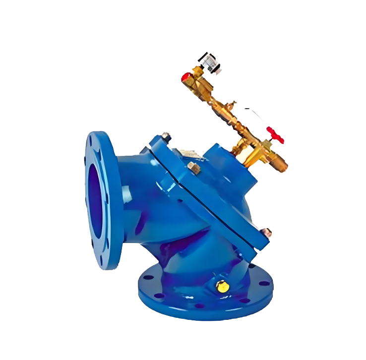
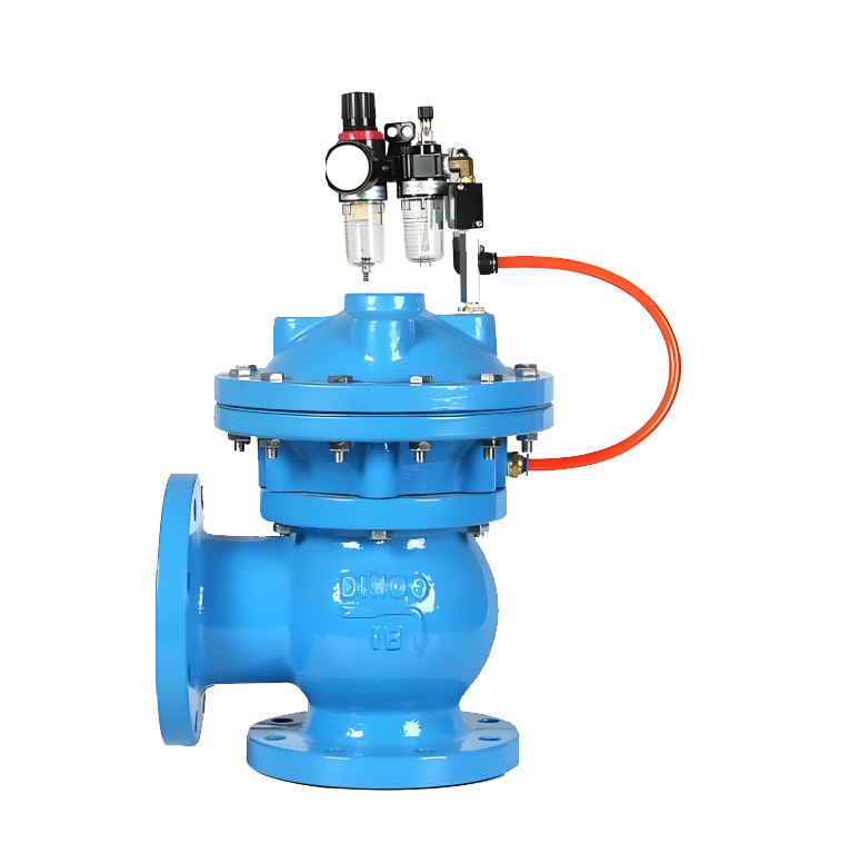
The 100S angle type diaphragm sludge discharge valve is a specialized angular valve utilizing rubber membrane as its actuator and sealing element, designed for intermittent automatic sludge or wastewater discharge at the bottom of water treatment systems. Its core mechanism drives the membrane actuator via external pressure sources (typically clean water or compressed air), enabling rapid valve stem and disc operation. When pressurized, the membrane chamber keeps the disc closed; when depressurized, the disc opens under medium pressure or self-weight to discharge. This valve employs angular channels for 90-degree redirection between vertical inlet and horizontal outlet, featuring a compact structure that effectively prevents sludge accumulation and clogging. As a critical component in sedimentation tanks, clarifiers, and sand filters, it enables timed and quantitative automatic sludge discharge.
100S Angle type Diaphragm Sludge Discharge Valve Product Diagram
Feature
1. The angular structure and anti-clogging design feature a 90-degree flow channel with vertical inlet connection to the pool bottom and horizontal outlet. This configuration abruptly alters the flow direction of the medium, effectively preventing solid particle deposition and clogging within the valve chamber. It ensures reliable operation and is particularly suitable for slurry media containing particles or fibers.
2. Thin-film actuation ensures high sensitivity and reliability: The core drive and sealing element is a rubber membrane, driven by the pressure difference between water or gas. The membrane completely isolates the control medium from the working medium, eliminating dynamic seal leakage points. It features rapid response, high thrust, and low control pressure requirements (typically 0.15–0.6 MPa for operation).
3. Dual Sealing and Maintenance Convenience: Valves typically feature a dual-sealing design, where the diaphragm serves as the primary seal while the valve disc and seat form the secondary seal, ensuring excellent sealing performance and airtight closure. When the diaphragm wears out, the valve can be replaced online by simply removing the valve cover without disassembling the pipeline, facilitating easy maintenance.
4. Corrosion resistance and long service life: The main flow components (valve body, valve cover) can be made of cast iron, ductile iron, or stainless steel, and the inner cavity can be lined with rubber. The rubber film and valve disc sealing materials (such as nitrile rubber, EPDM rubber) are wear-resistant and resistant to mud and water corrosion, ensuring a long service life.
5. Automatic control, energy-efficient and high-performance: It can be easily connected with solenoid valves, time relays, or PLCs to achieve fully automatic program control (timed and batch sludge discharge). The valve consumes only a small amount of water or gas during the instant opening/closing process, significantly saving water or electricity compared to normally open sludge discharge, thereby reducing operating costs.
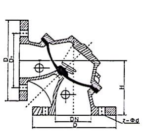
100S Angle type Diaphragm Sludge Discharge Valve Structure Diagram
List of Component Names and Materials
| Part Name | Common materials |
| body, cover | Cast Iron, Ductile Iron |
| disc、spring | stainless steel |
| diaphragm | Nylon strong SX rubber |
Performance Specification Sheet
| Performance Specification Sheet | ||||
| Nominal Pressure | 1.0 | 1.6 | 2.5 | MPa |
| Strength test pressure | 1.5 | 2.4 | 3.8 | |
| Sealing test pressure | 1.1 | 1.76 | 2.8 | |
| Applicable Temperature | ≤80 | ℃ | ||
Standard requirements for external dimensions
1. The structural length of the valve shall comply with the standard of GB/T12221
2. Connecting flanges according to GB/T17241.6 standard
Standard requirements for external dimensions
1. The structural length of the valve shall comply with the standard of GB/T12221
2. Connecting flanges according to GB/T17241.6 standard
100S Angle type Diaphragm Sludge Discharge Valve Outline Diagram
Outline Dimension Table
| Nominal diameter | Key dimension | |||
| H | D | D1 | z-φd | |
| 80 | 140 | 195 | 160 | 4-18 |
| 100 | 150 | 215 | 180 | 8-18 |
| 150 | 185 | 280 | 240 | 8-23 |
| 200 | 245 | 335 | 295 | 8-23 |
| 250 | 340 | 395 | 350 | 12-23 |
| 300 | 395 | 445 | 400 | 12-23 |
-
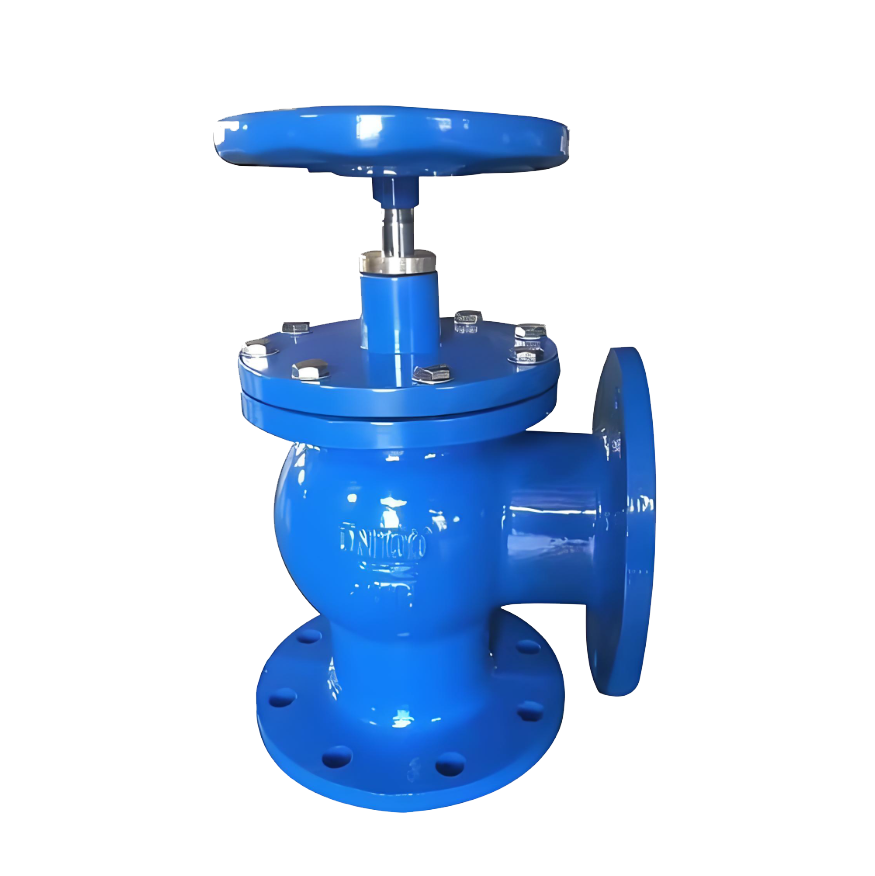 SD44X Manual Sludge Discharge Valve
Model:
SD44X-10 / SD44X-16 / SD44X-10Q / SD44X-16Q / SD44X-25QSpecification:
DN80-DN300Pressure:
PN10~PN25Material:
Cast Iron, Ductile Iron -
 JM644X Pneumatic Sludge Valve
Model:
JM644-10/JM644-16/JM644-10Q/JM644-16Q/JM644-25QSpecification:
DN100-DN400Pressure:
PN10~PN25Material:
Cast Iron, Ductile Iron -
 HS742X Stainless Steel Hydraulic Pool Bottom Sludge Discharge Valve
Model:
HS742P-10P/HS742P-16P/HS742P-25PSpecification:
DN150-DN500Pressure:
PN1.0~2.5MPAMaterial:
stainless steel
Address:No. 1, Linxia Road, Sanqiao Industrial Zone, Oubei Sub-district, Yongjia County, Zhejiang Province| Switchboard:0577-67198981| mobile:+8613388552747| Email:sales@shanliuvalve.com|
COPYRIGHT © Zhejiang Shanliu Valve Technology Co., Ltd. Main Business: Water Valve Industrial valve|
浙ICP备2026020749号![]()